ARISE Adaptive Design designs and fabricates customized equipment and devices for children with disabilities. Fisher-Price donated over 50 of their Power Wheels Wild Thing ride-ons to ARISE to be adapted into custom mobility devices through structural and electronic modifications. These devices act as low-cost starter wheelchairs for children in need.

This project has been ongoing for the past five years, with several unfinished versions put into use along the way. As part of my internship at ARISE Adaptive Design, I was put in charge of redesigning and finalizing the armrest adjustment mechanism, as well as creating an adjustable headrest design using 3D printing and other low-cost materials.
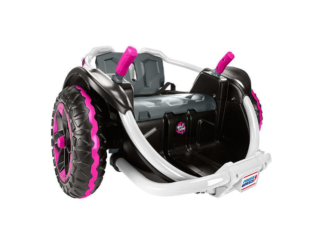
Power Wheels Wild Thing Battery Powered 12V Spinning Ride On Vehicle, Pink
(Full Assembled Prototype At Bottom Of Page)
The headrest and armrest systems were designed and modeled by me. While I made modifications to the CNC'd seating including fastening holes, slots, and some shape adjustments, the original seating design was not mine. Similarly, the electronic modifications were designed by someone else. The materials list below represents the bulk of my contributions to the project.
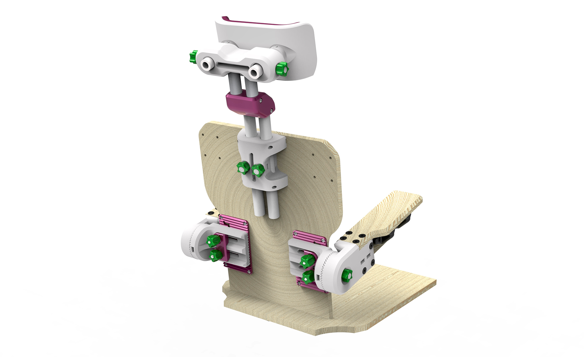
Modeled in Onshape, rendered in KeyShot, and exploded drawing produced in SolidWorks.
Armrest PROCESS
Original Armrest System
The redesign process for the Wild Thing Armest started with deconstructing the original system (shown above) to understand what is necessary and what can be redesigned. From conversations with my advisor, the collective goal for the armest was defined as having adjustability horizontally, vertically, and diagonally.
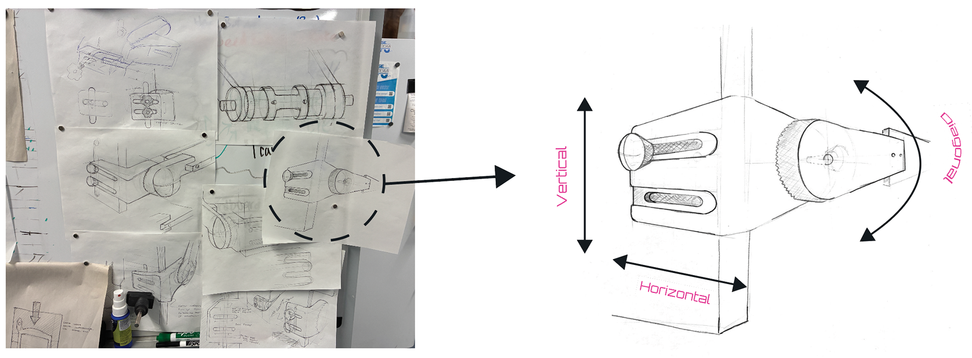
Quick Sketches
I decided to get rid of the PVC rail entirely and replace it with two printed parts connected to the seatback with knobs through a linear slot, allowing adjustable movement vertically and horizontally. The printed part would have a connected arm, linked with circular patterned teeth and tensioned with a knob that would allow for diagonally adjustable movement.
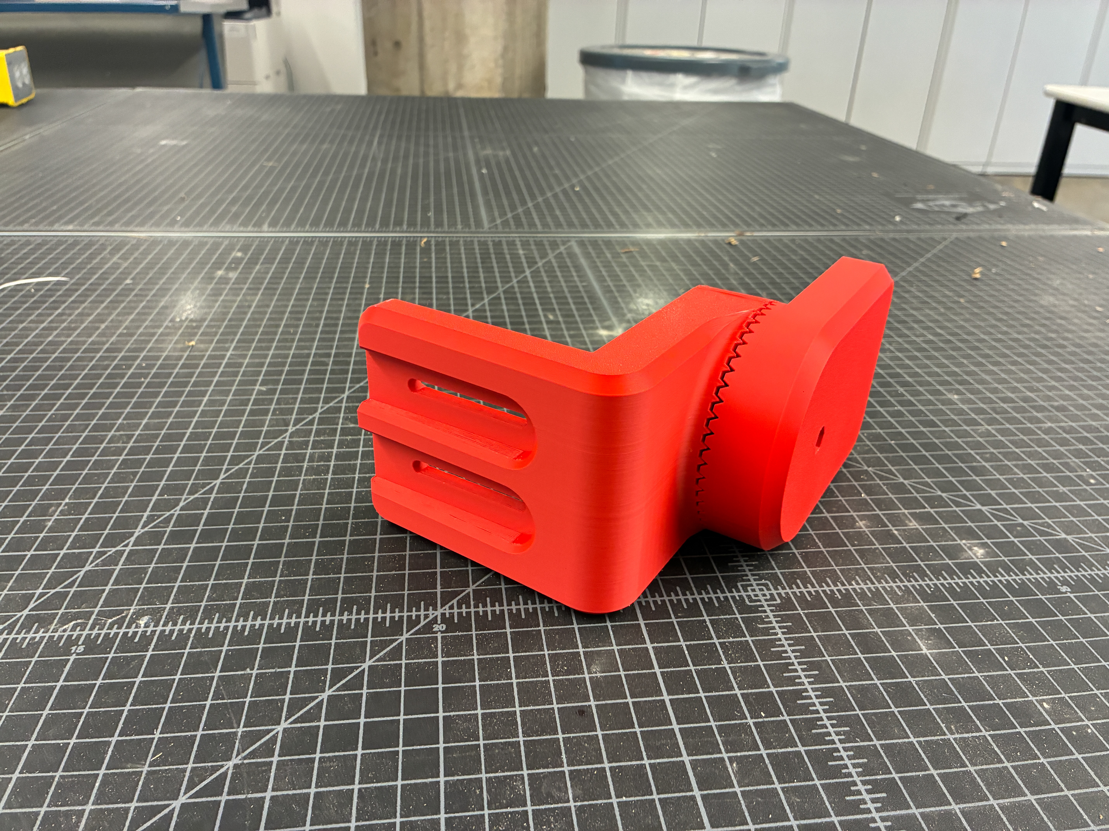
First Prototype
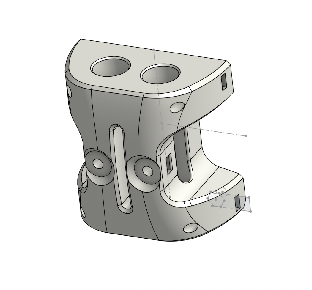
From the sketches I went immediately into CAD to prodcuce the first prototype, the circular patterned teeth system worked great with the tensioned knob, however, the part was too large and could be cut back in many different areas, Adding a circular recess for the knob on the outer face and starting to think about how the printed part would interface with the wood armrest was the next step.
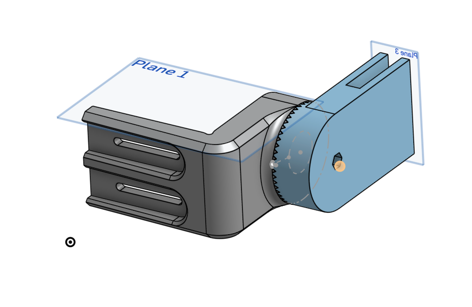
Updating Original Model
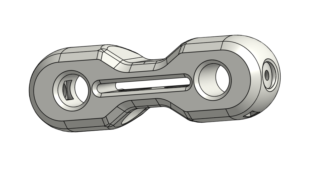
Second Prototype
The second prototype was a notable improvement, the height of the part was now 3in instead of 3.5in, making a huge difference in print time and overall room on the seatback. This is also where the knobs started to come in for testing. The knobs designed for this piece contained an embedded 1/4" x 20 nut allowing the knob to tension the armrest to the seat back via a carriage bolt. A regular bolt was used for the diagonal adjustability, also with a captive nut knob.
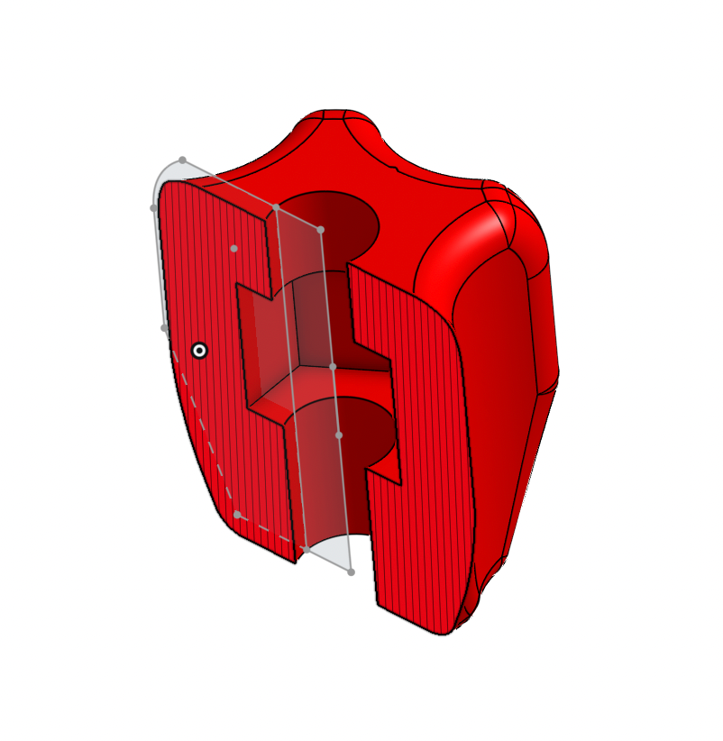
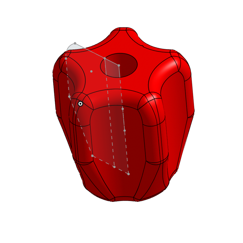
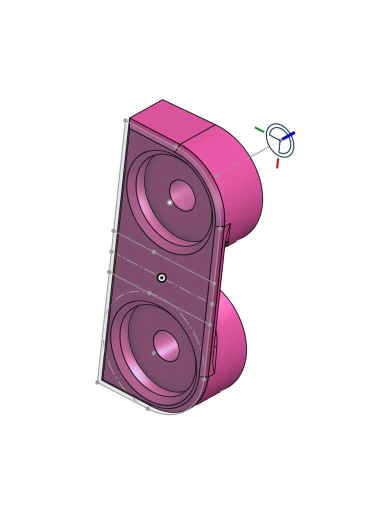
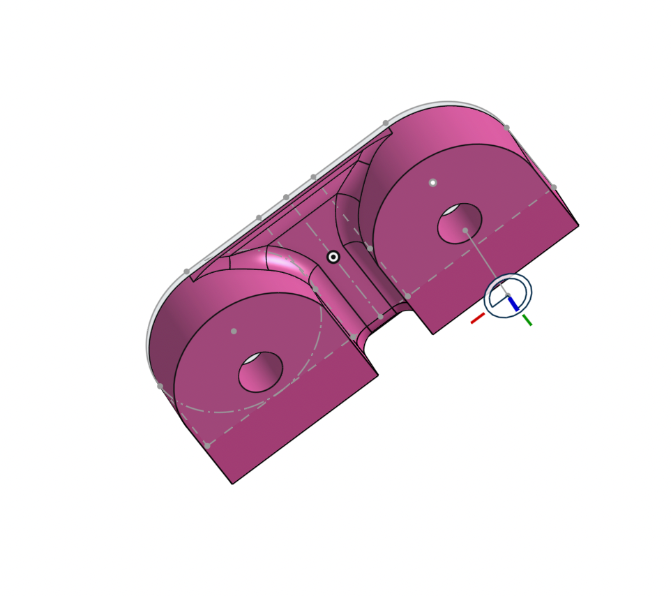
1/4" X 20 Embedded Knob
Inserting Embedded Nut
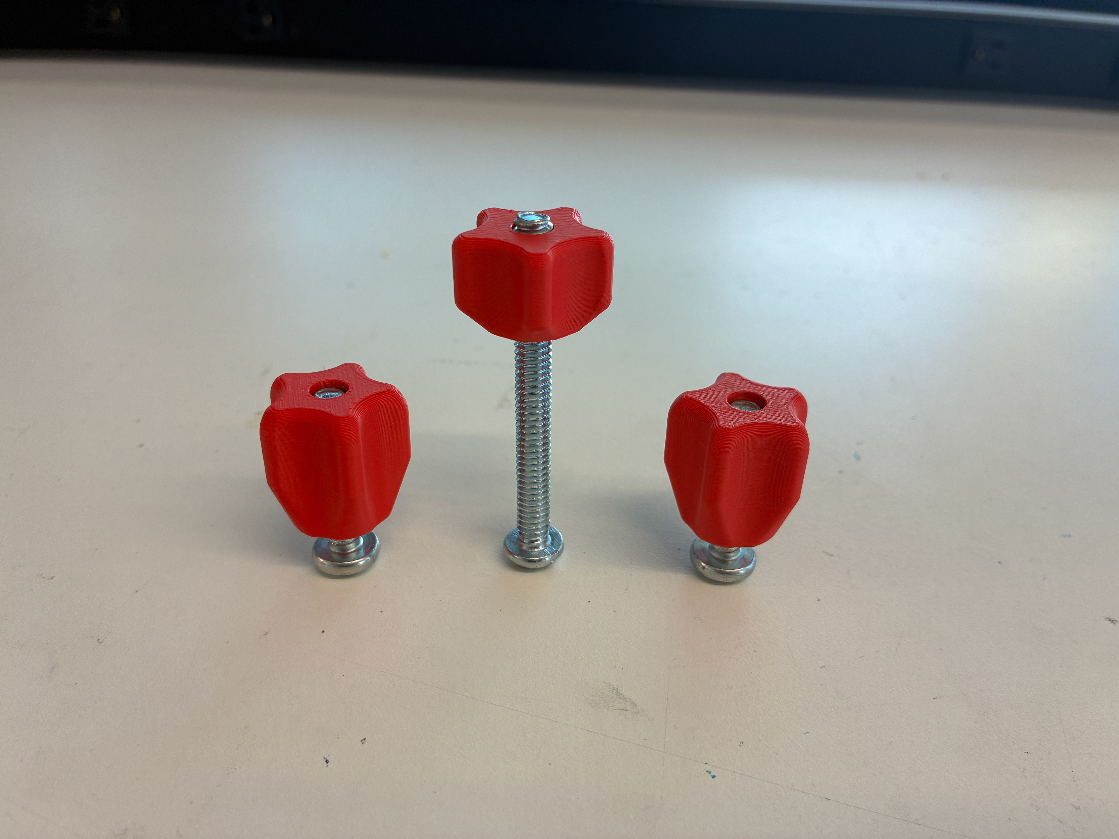
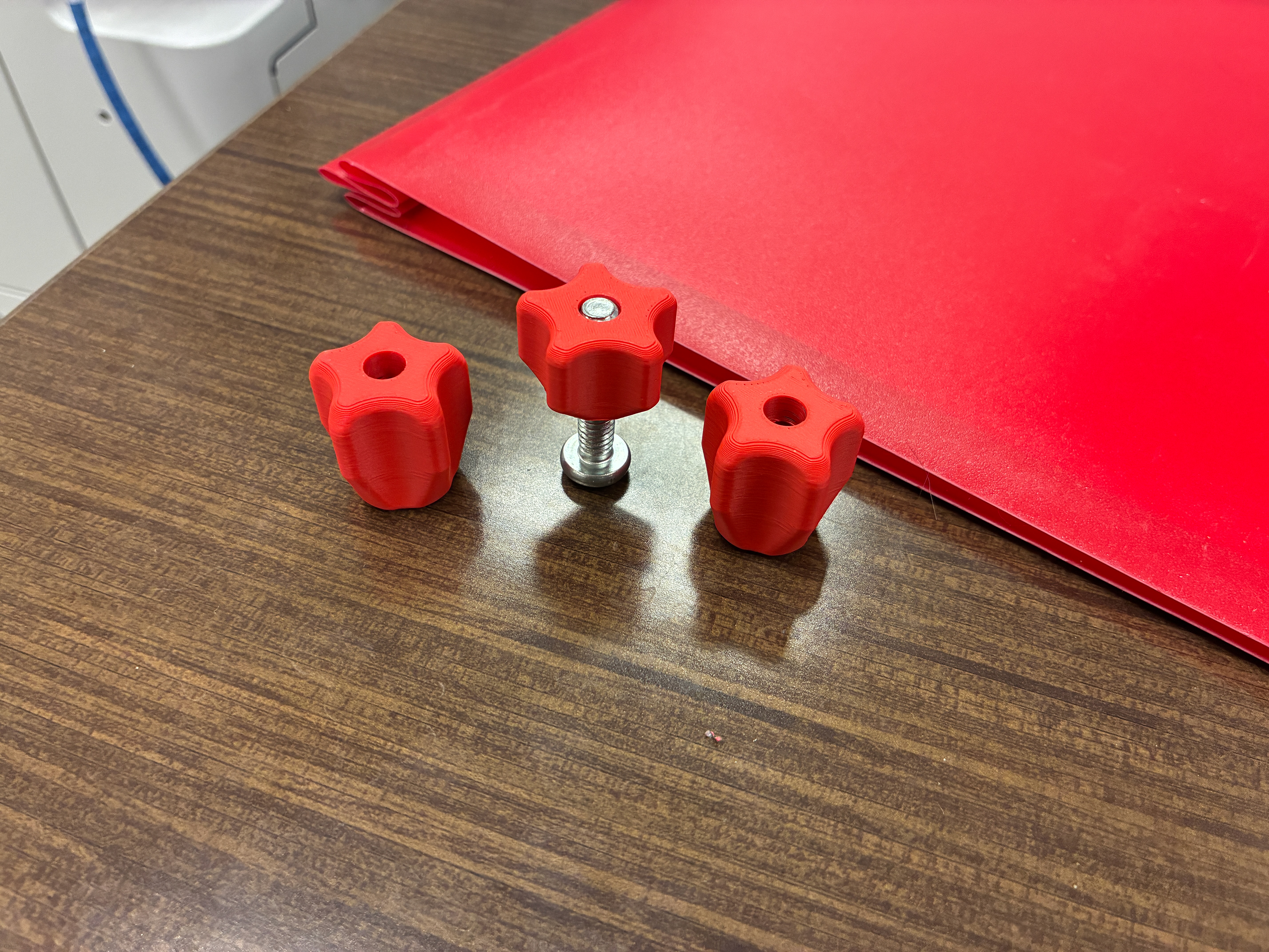
Final Printed 1/4" X 20 Embedded Knob
Unprofessional Durability Test
It was helpful through the prototyping process to put these models through some real wear to see what aspects need to be improved. From this test it was clear that certain parts of the model needed to be made thicker. It also became clear that the pivot point needed to be closer to the seatback, this would allow the armrest to align closer with the users elbows.
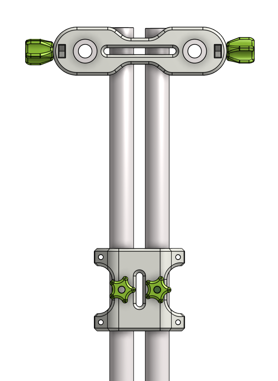
Another valuable takeaway from this test was realizing that when pressure is applied downward or upward to the part, the knobs aren't tensioned enough the keep the part from pivoting. From this discovery a new piece was added to the model that I call the "Collinear Straight Slot". This new piece attaches to the back slots and keeps the two knobs collinear with each other at all times, getting rid of the ability for the part to pivot on the seatback,
Collinear Straight Slot
Updated Model With More Material | With Pivot Point Closer To Slots
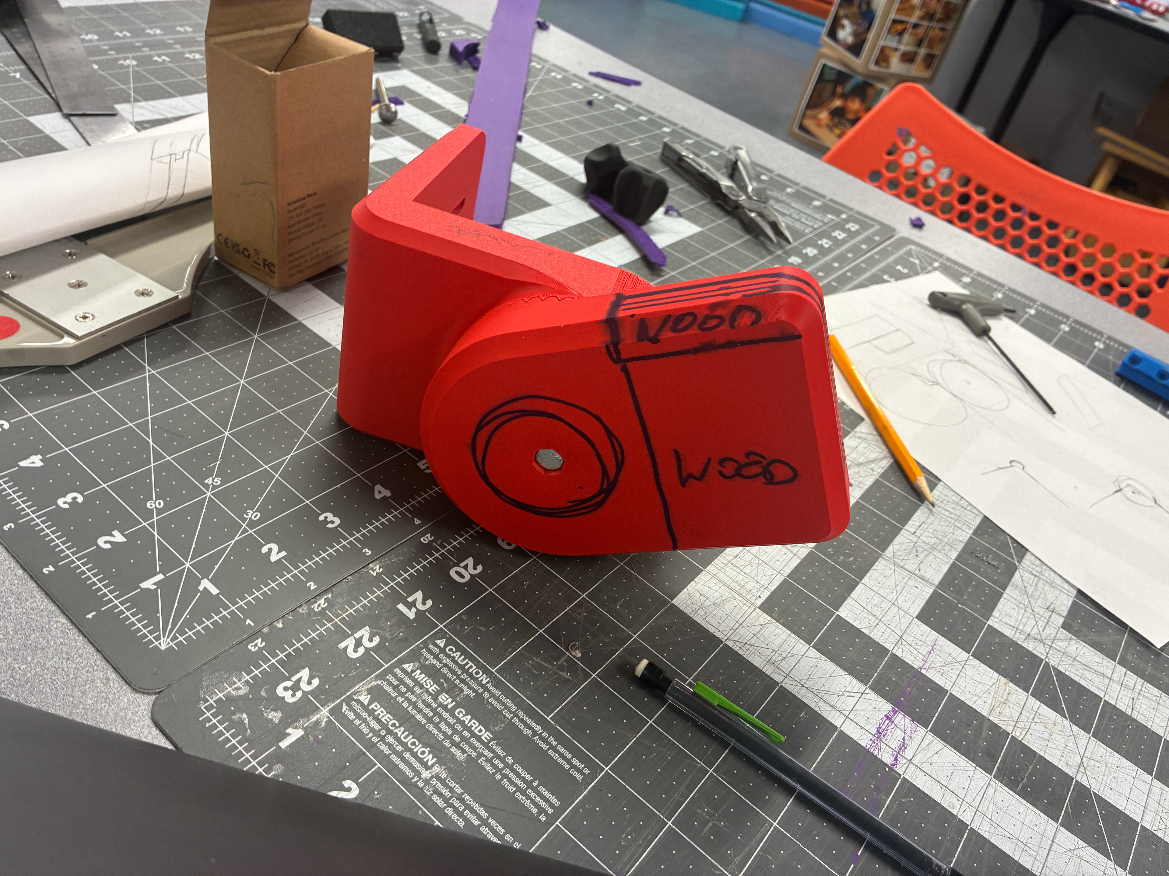
Updated Model With Imagined Wood Interface
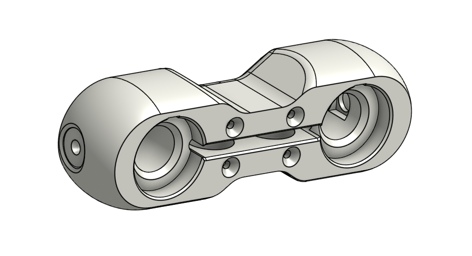
Third Prototype With Collinear Straight Slot
The third prototype worked well and the collinear straight slot fixed the pivoting issue. The main concerns now were pushing the pivot point back even further and adding embedded nuts and screw holes for the wood interface
Fourth Prototype
For the fourth prototype I pushed the pivot point back as far as the model could go, my advisor decided that it still wasn't far enough. The third photo above showcases that if you pivot the arm 180 degrees, the armrest aligns much better with the seatback.
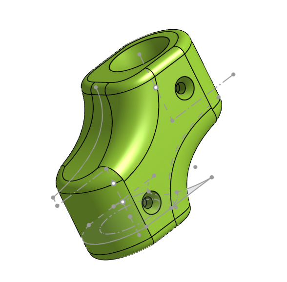
Fifth Prototype
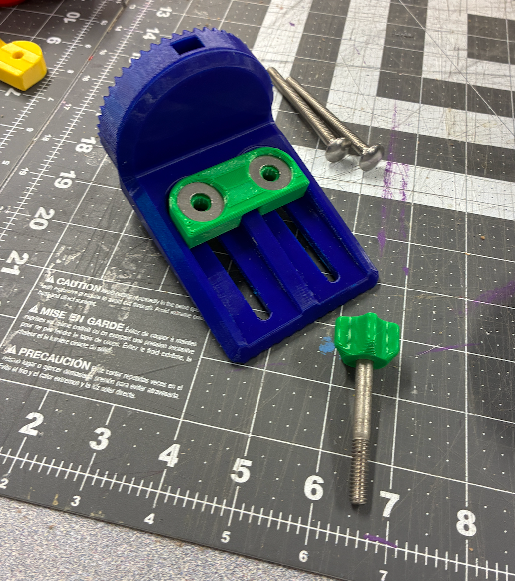
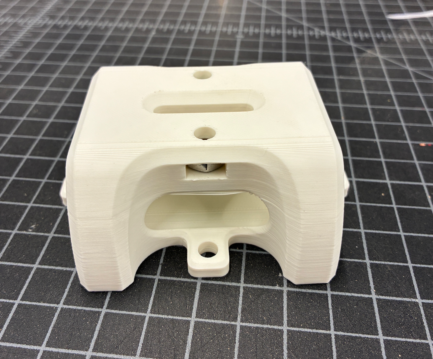
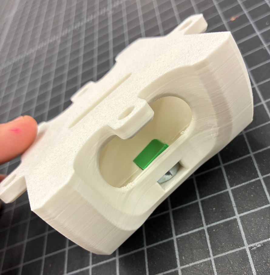
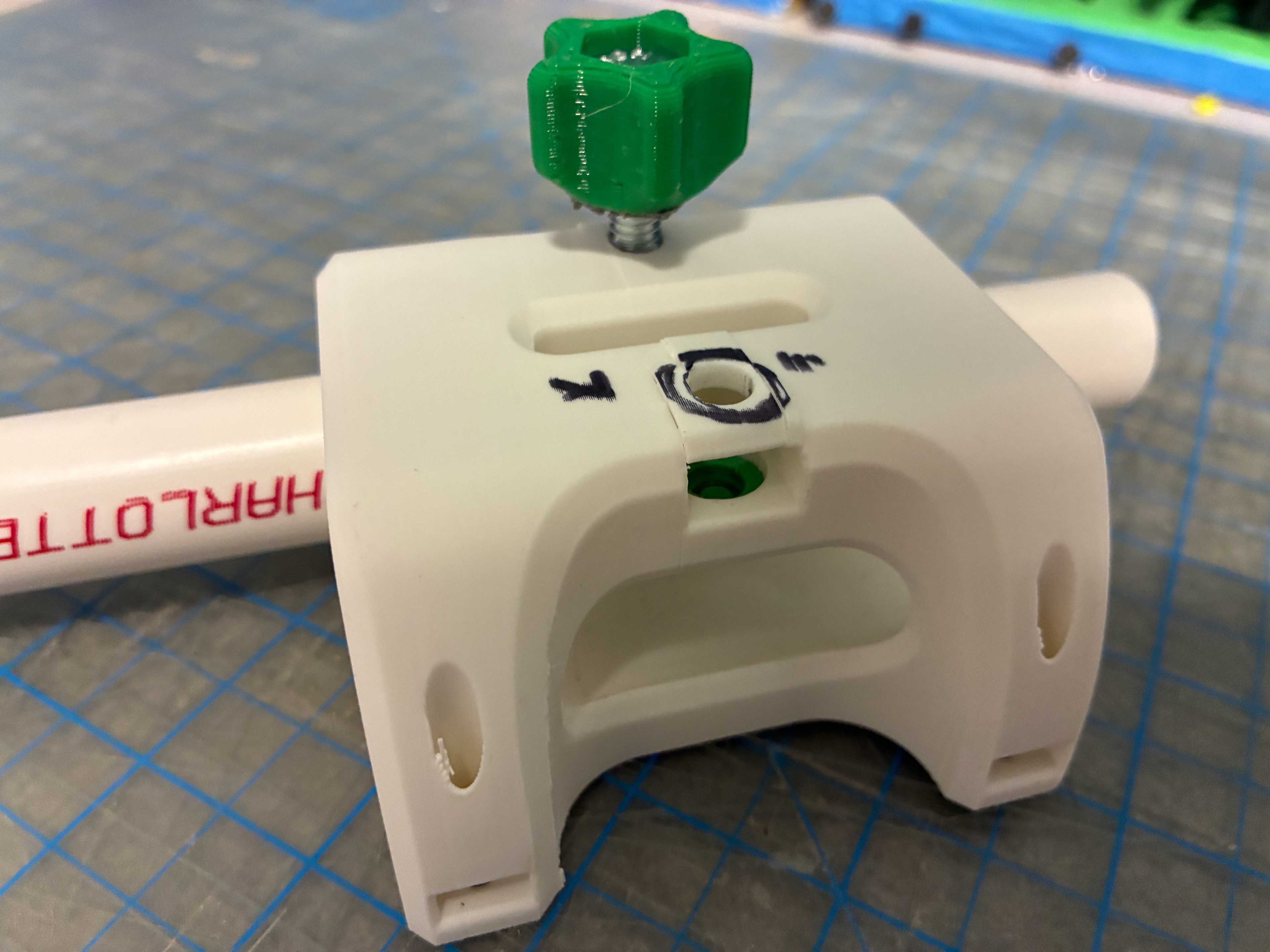
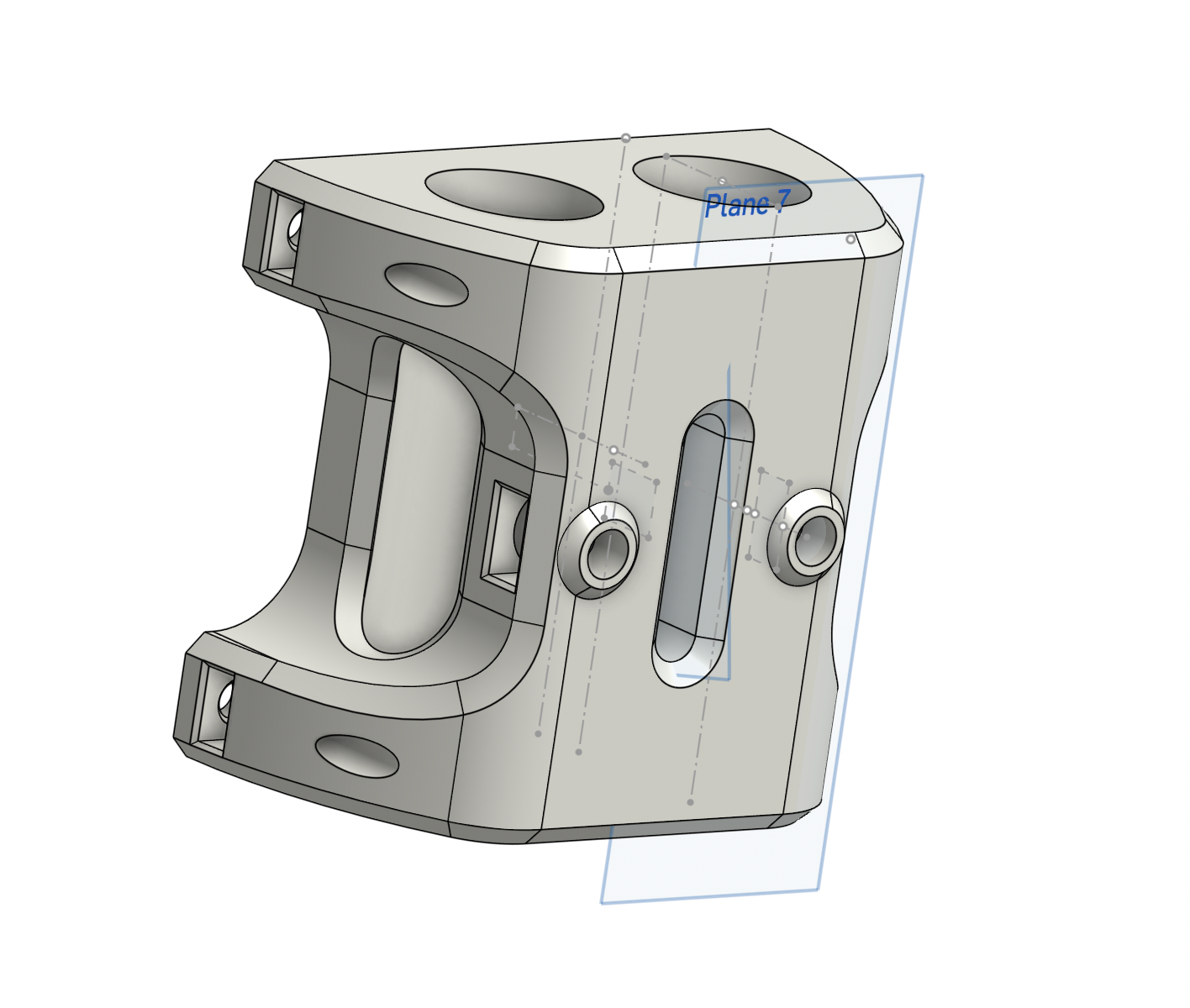
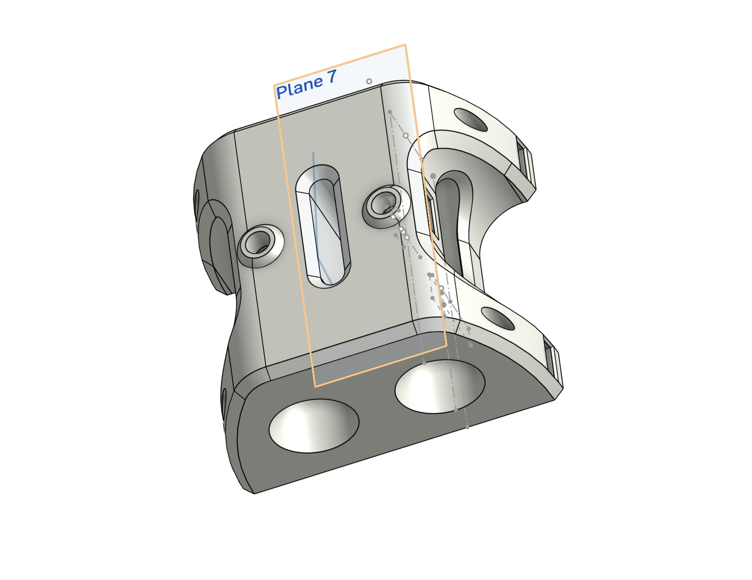
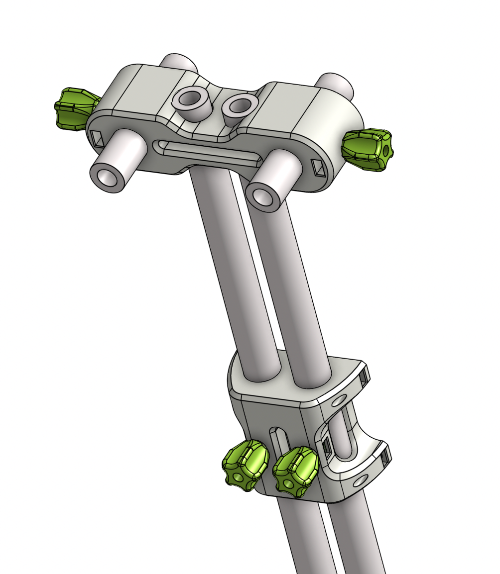
The fifth prototype featured the pivot point extended behind the seatback and a new side knob. Because the back slot wall was now in front of the pivot point there was no room to have a bolt go through and extend to a knob. This was fixed by adding an embedded nut into the fixed part and having a knob with a inserted bolt attach (green knob above).
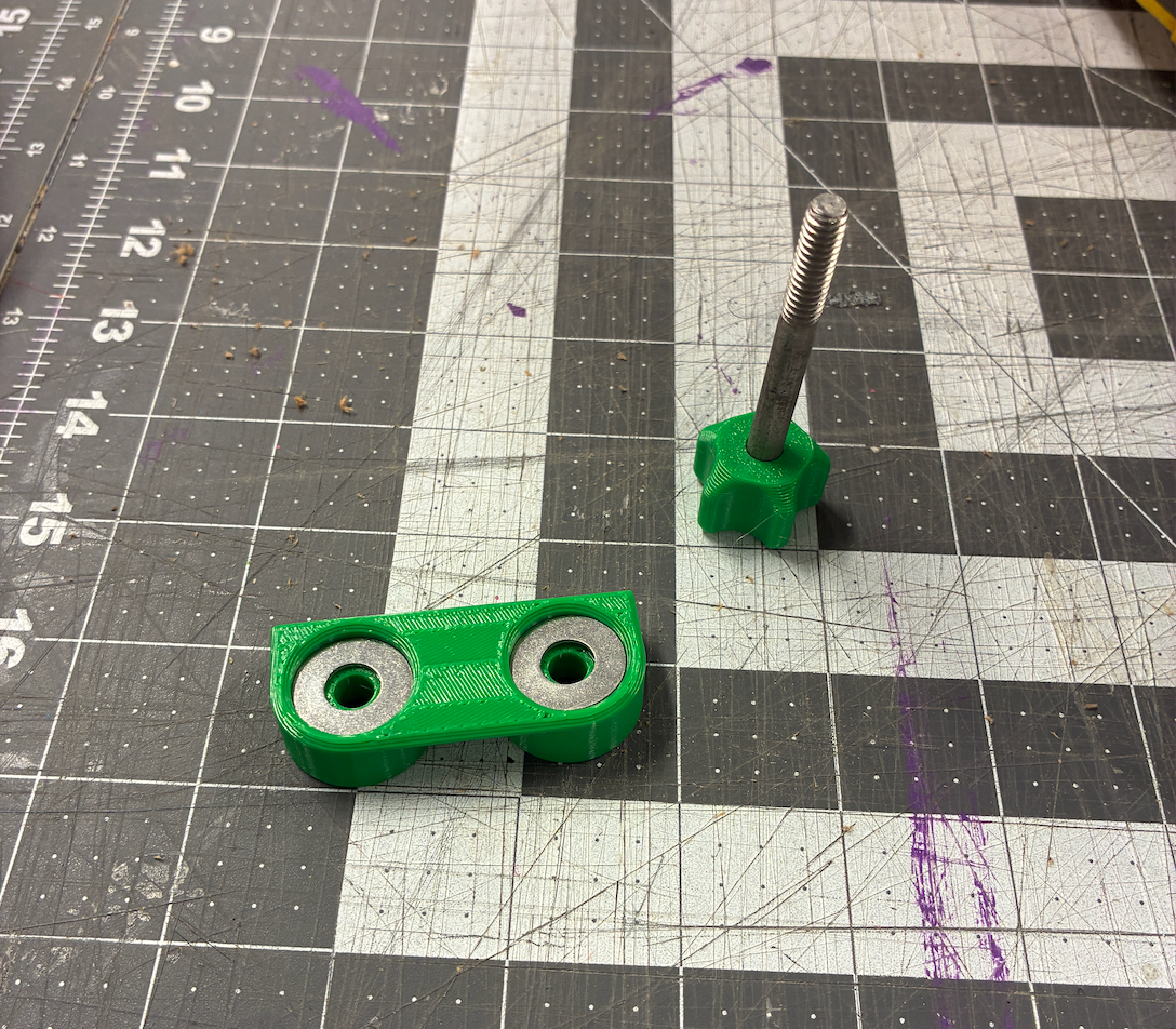
Washers Added To Collinear Straight Slot
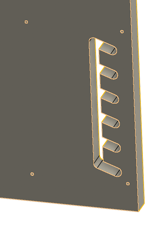
Seat Back Armrest Cutout Slot System
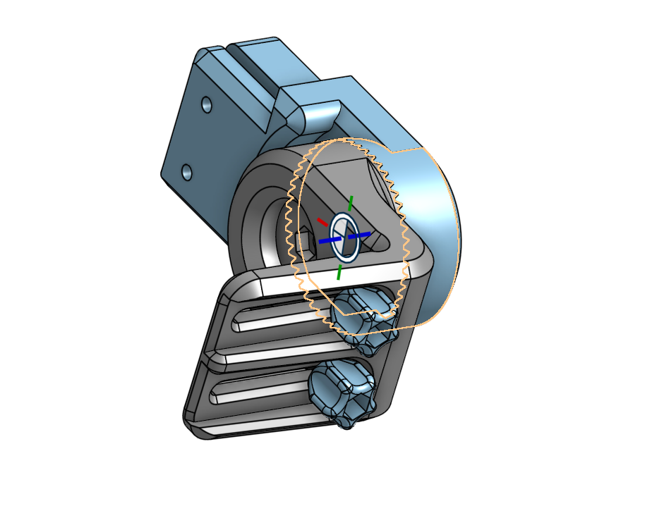
Although the washers and collinear straight slot kept the part from pivoting, it was devised that a teethed printed part could interface with the back of the fixed piece and the seatback to secure it further (Waffle).
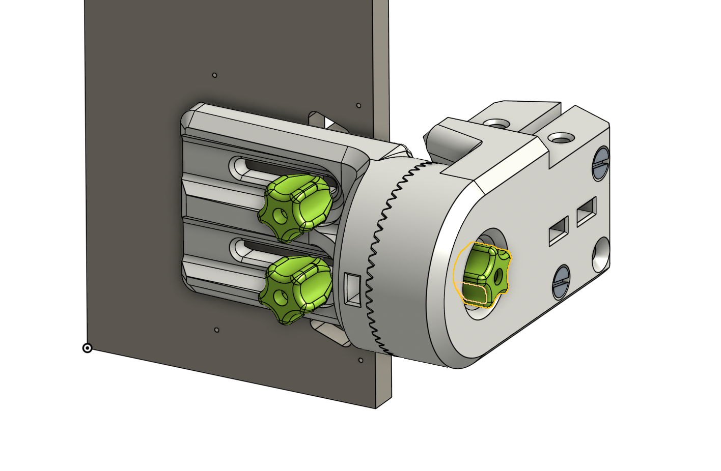
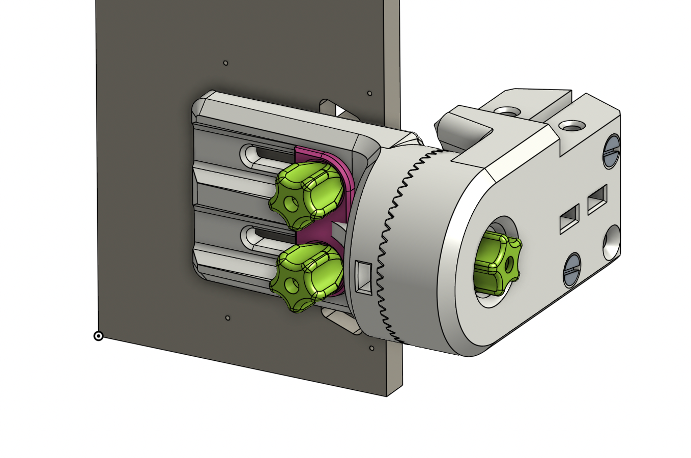
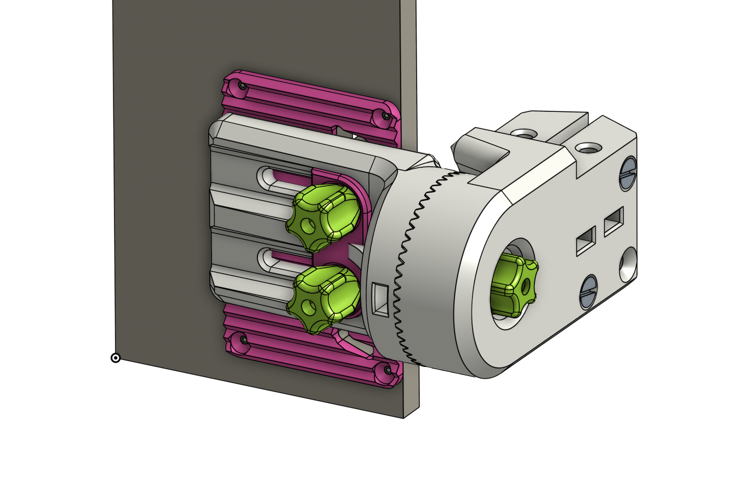
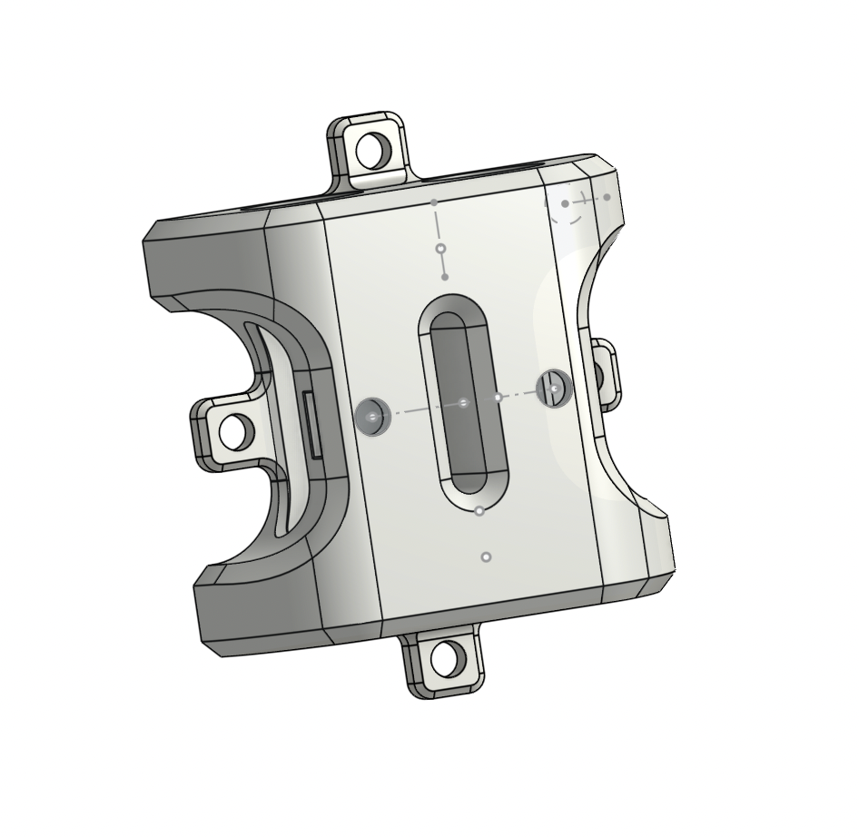
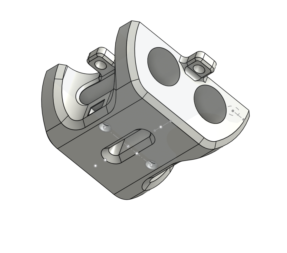
Adjustment Mechanism with Knobs | with Knobs and Straight Slot | With Knobs, Straight Slot, and Waffle
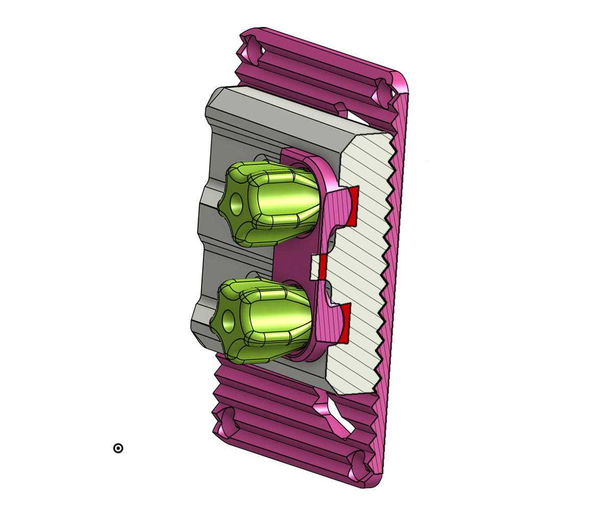
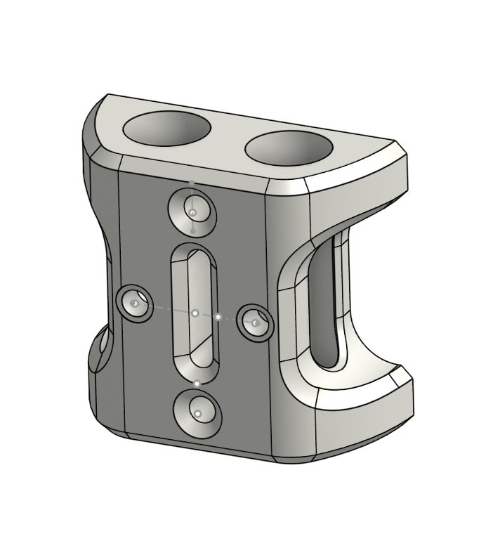
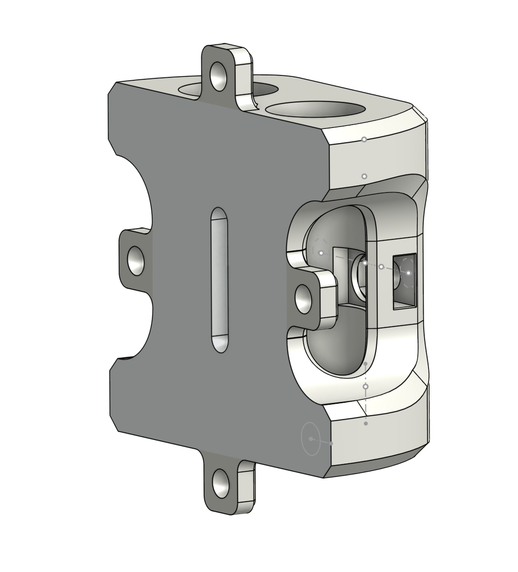
Seatback "Waffle" Attachment Section View
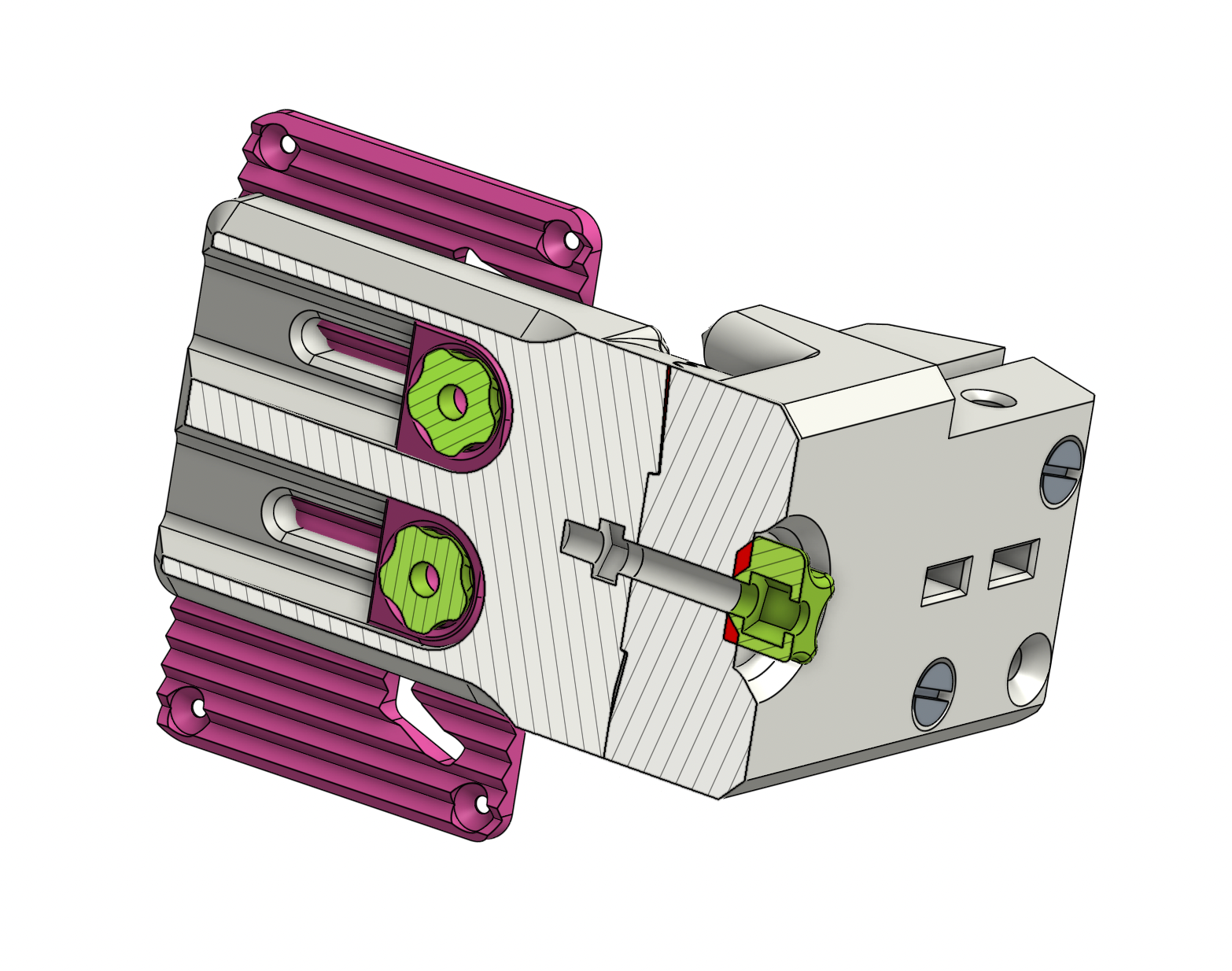
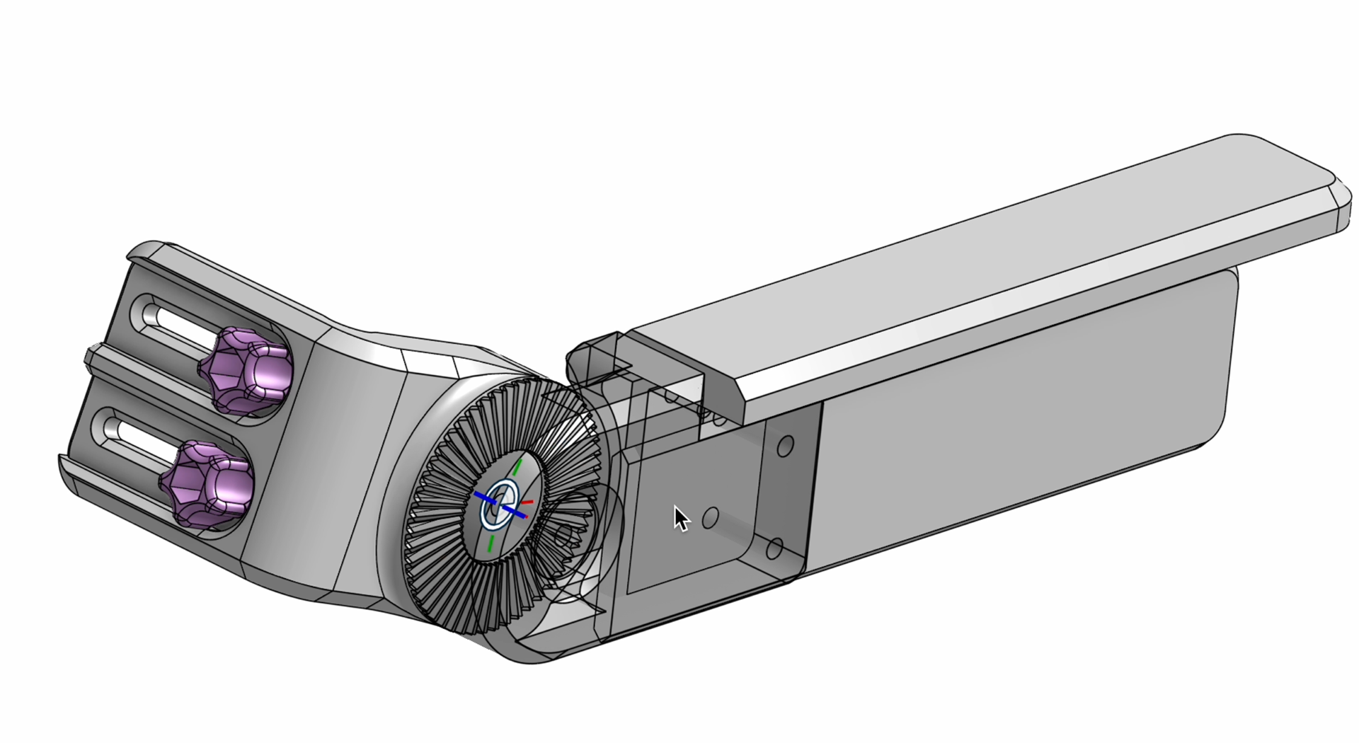
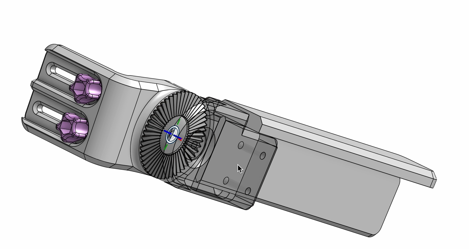
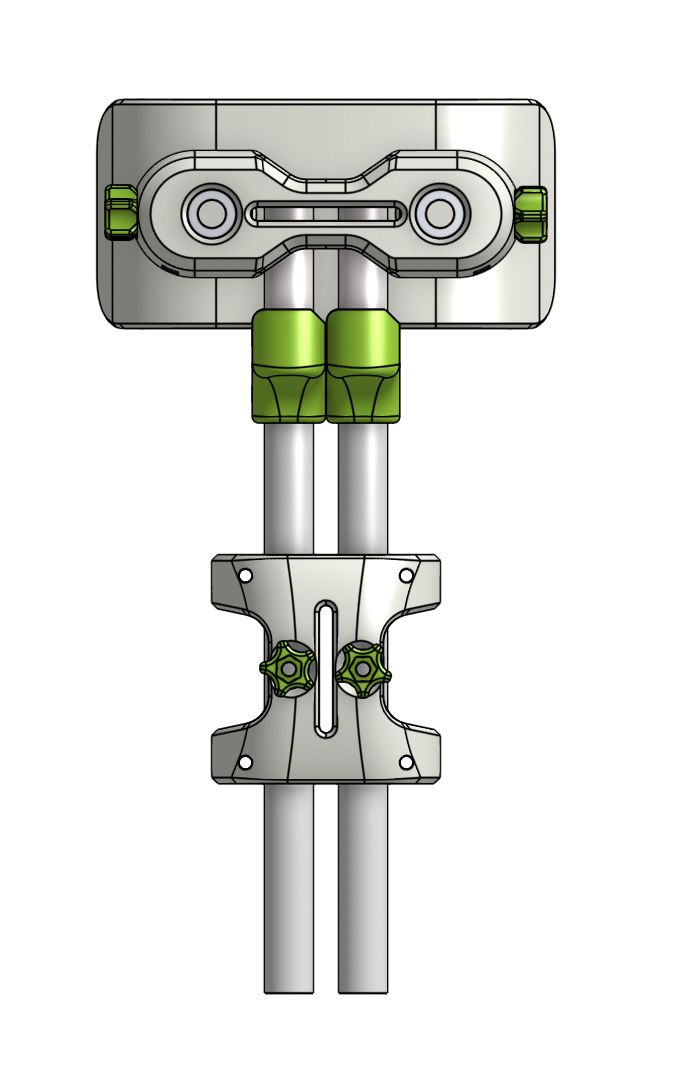
Adjustment Mechanism Section View
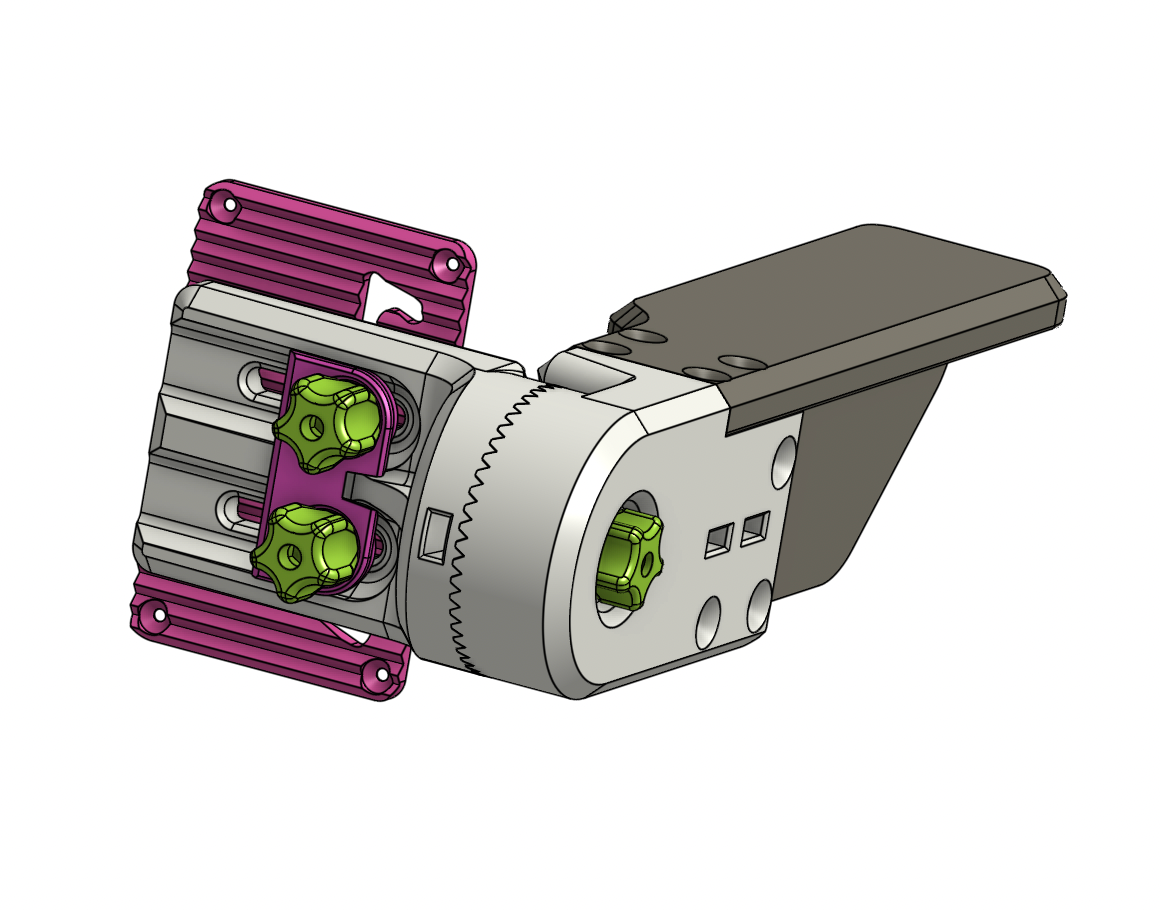
Adjustment Mechanism With Armrest
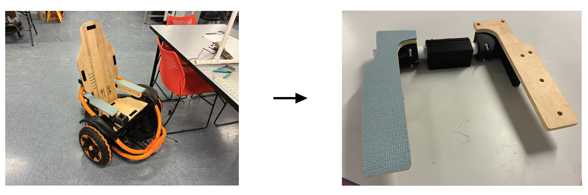
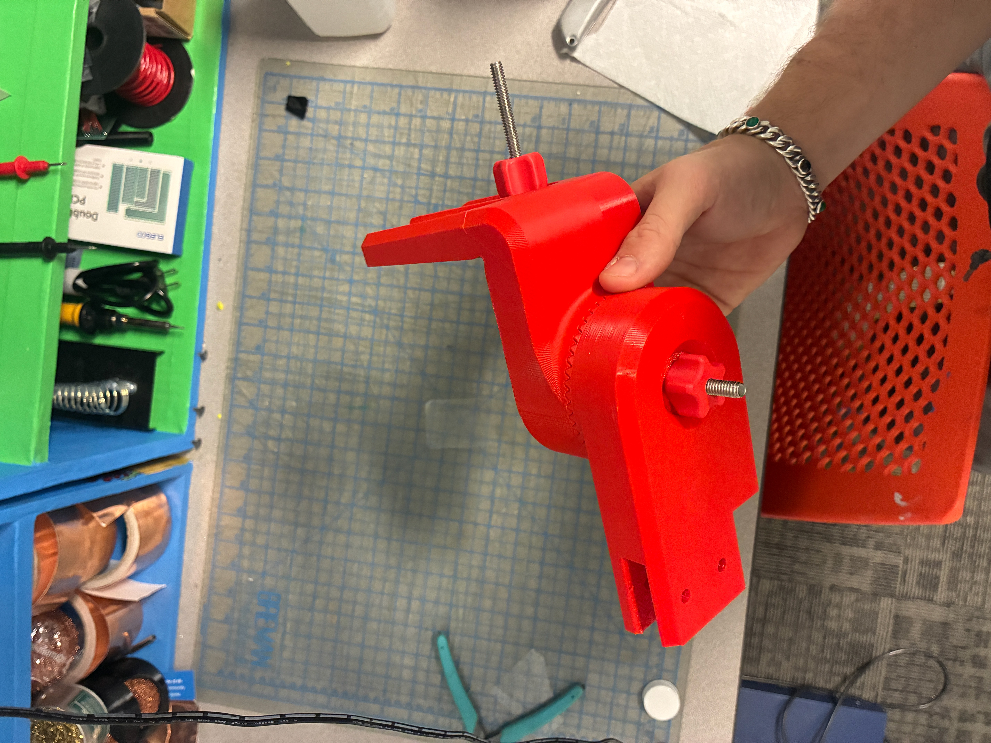
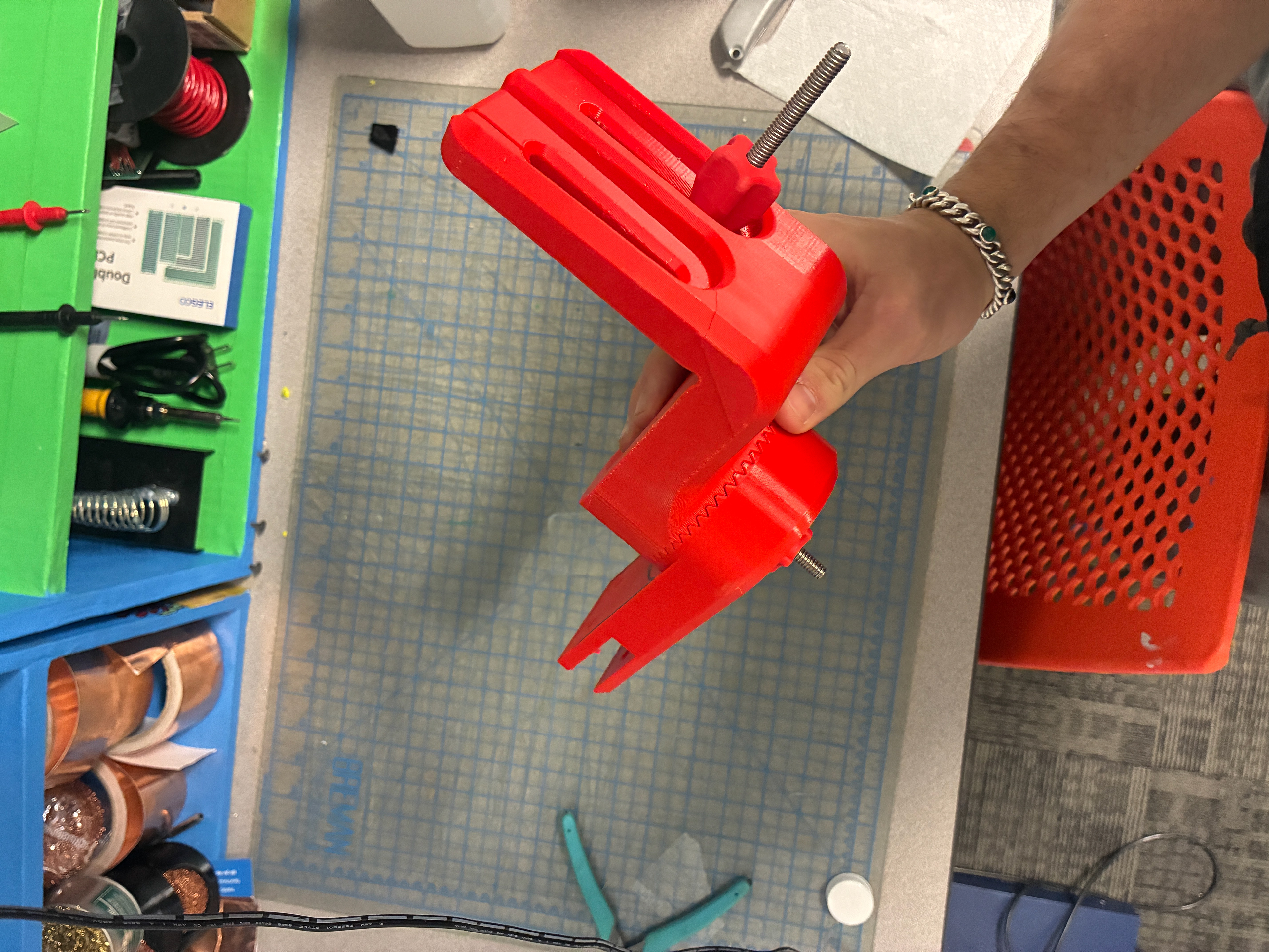
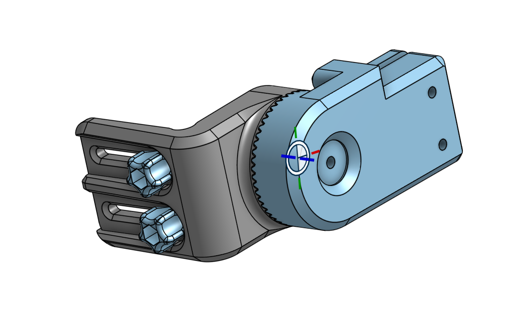
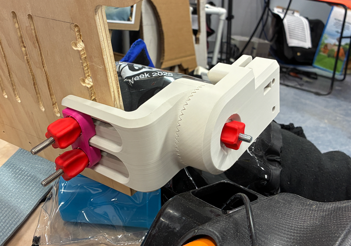
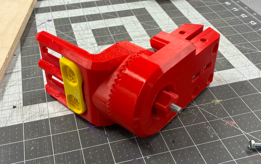
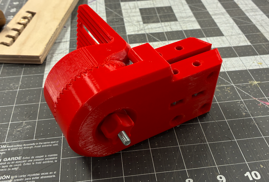
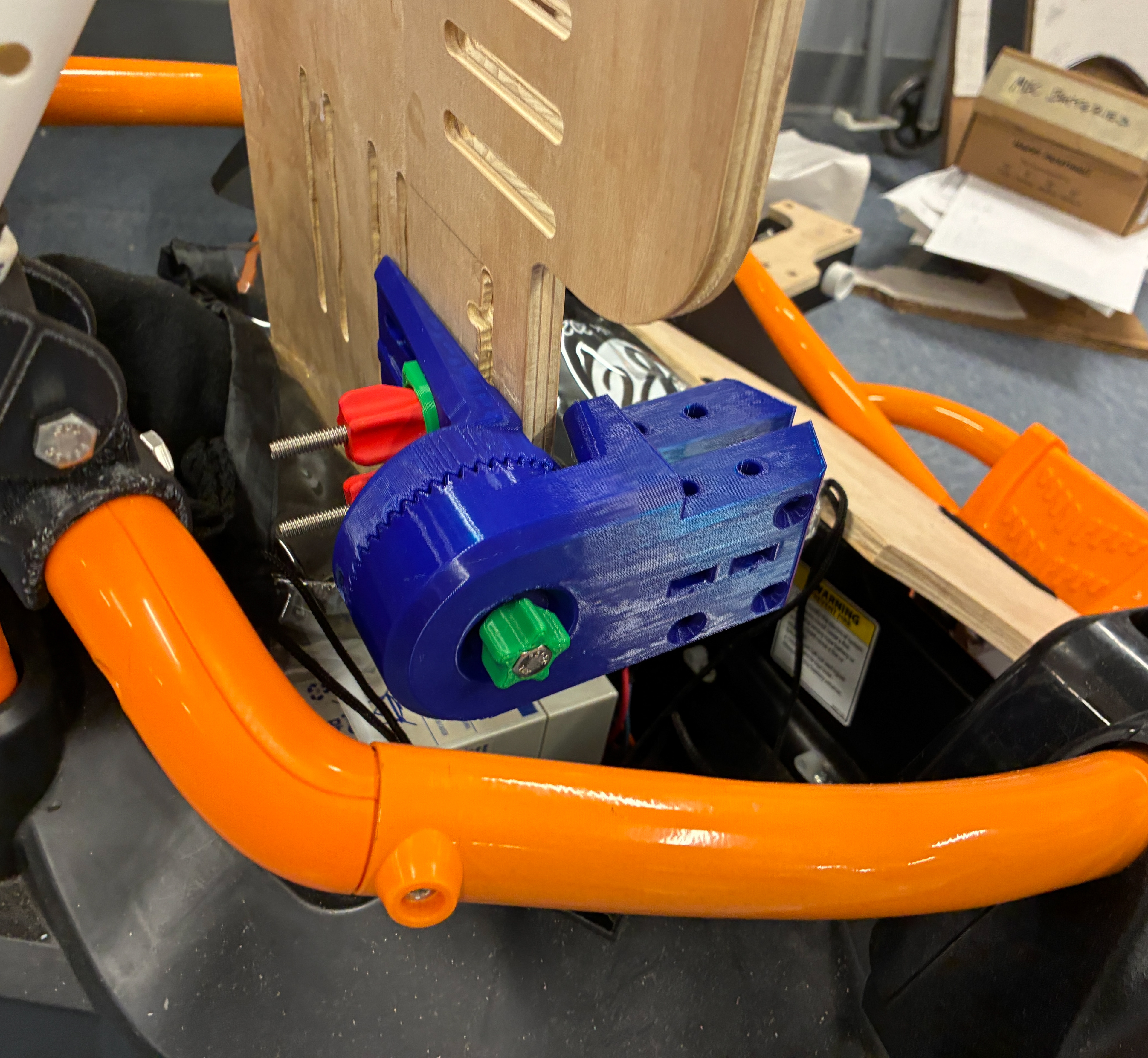
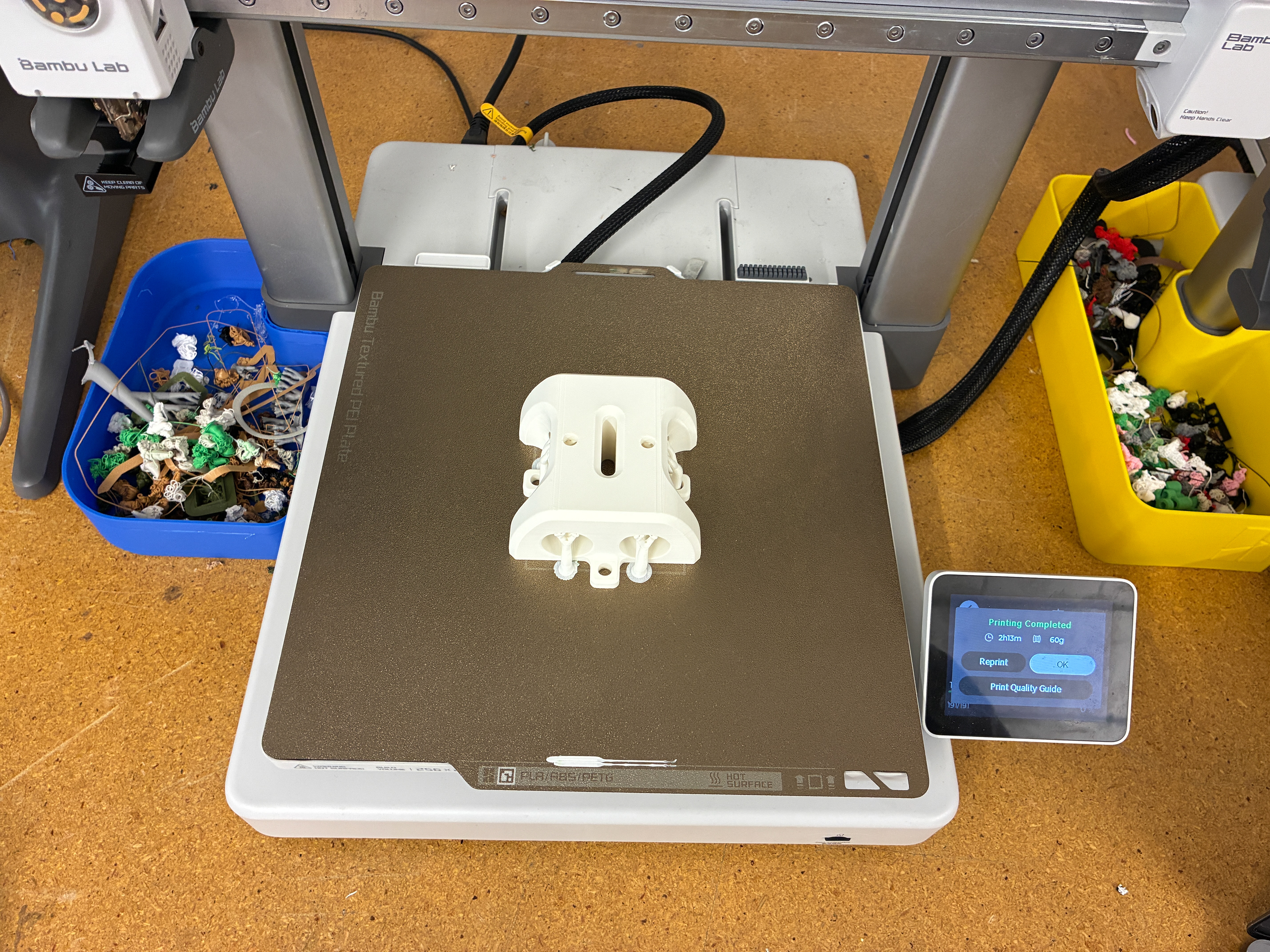
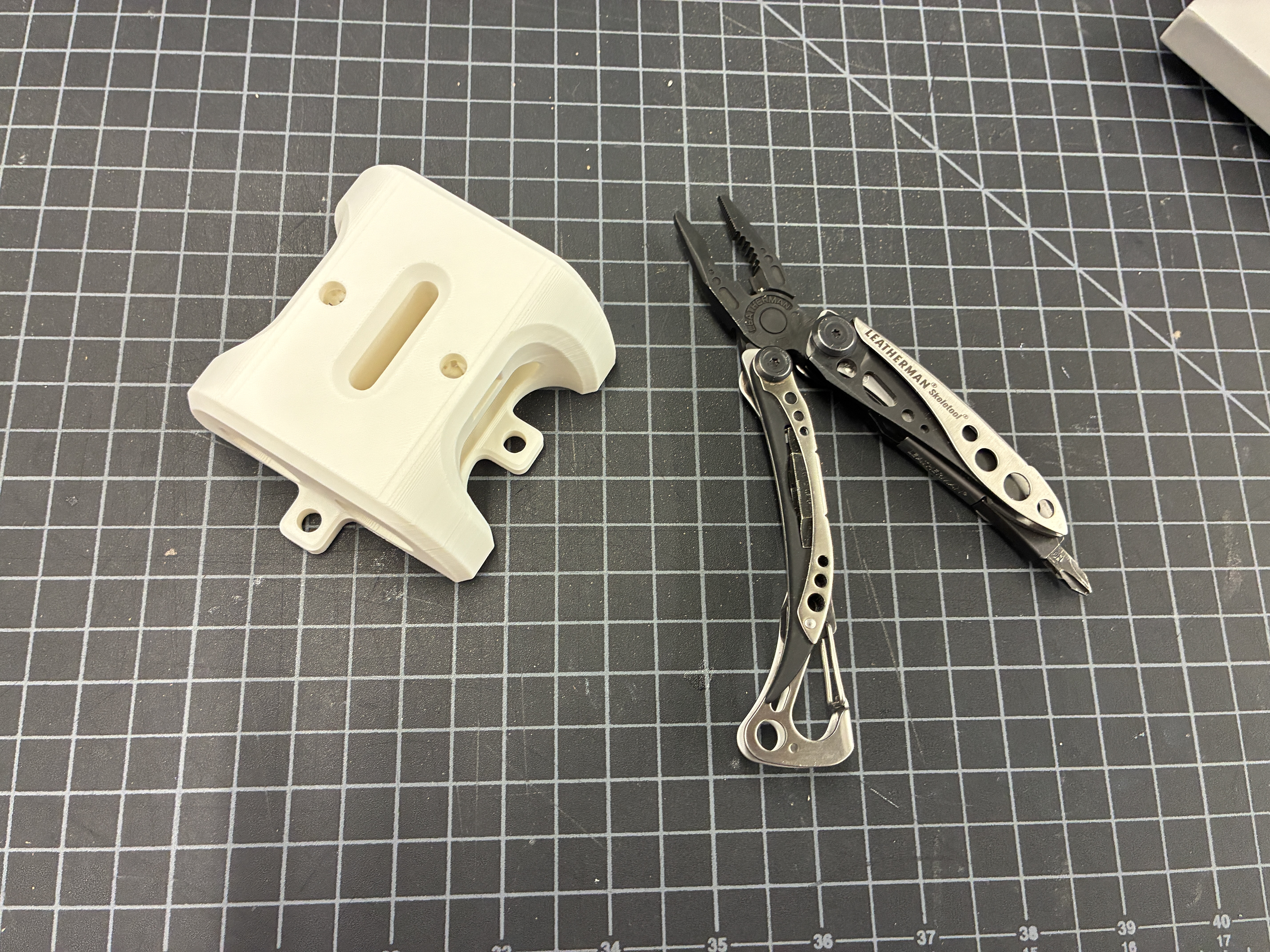
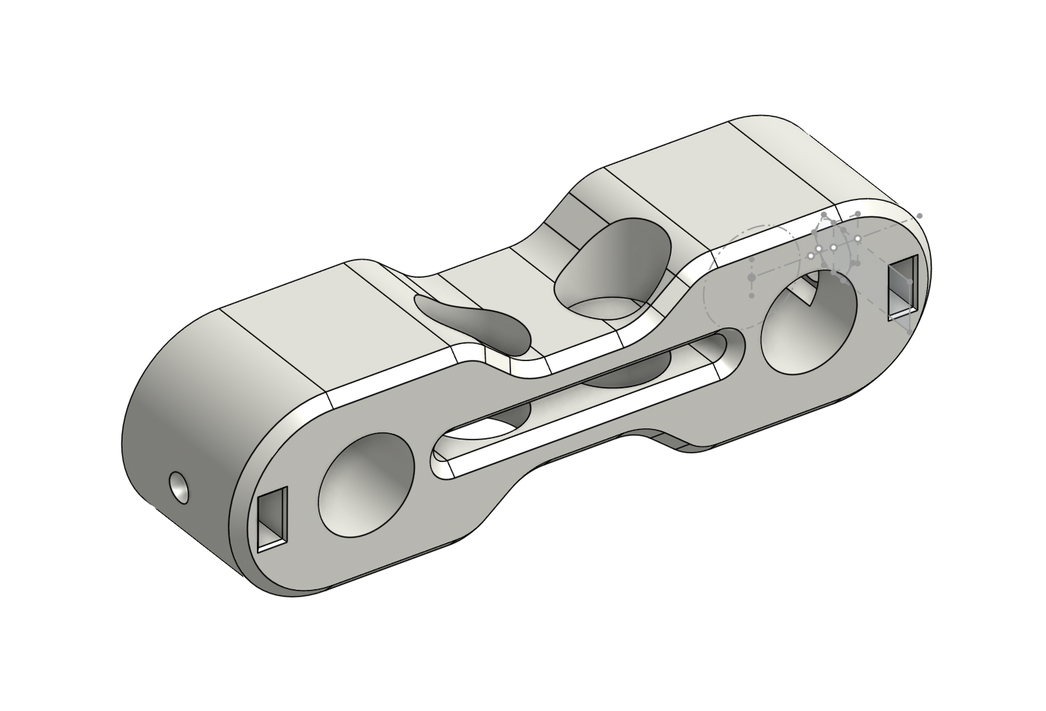
Armrest Adjustment Mechanism (Sixth Prototype)
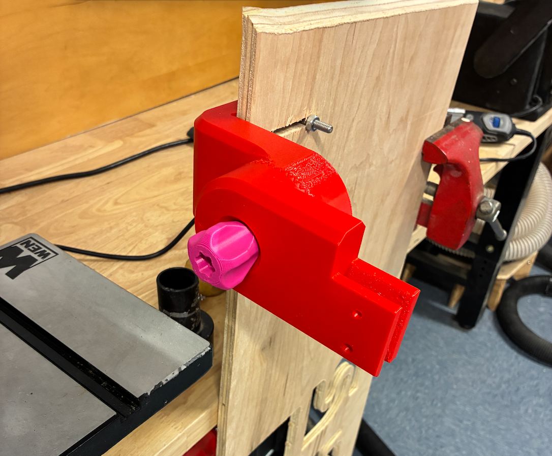
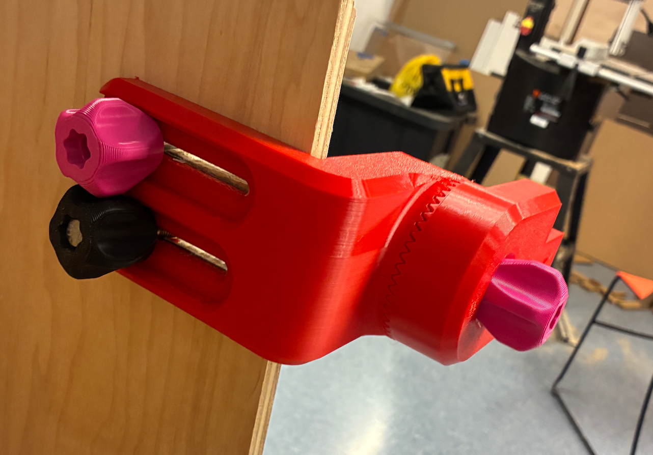
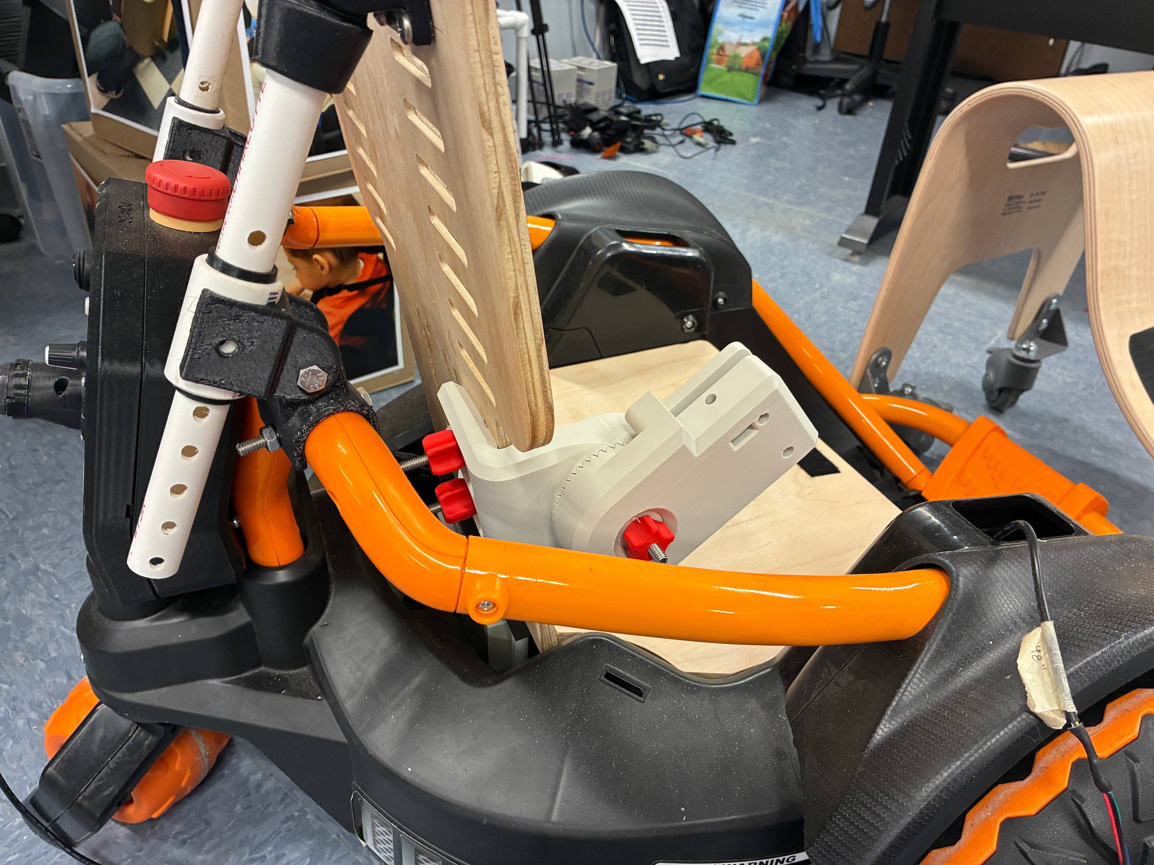
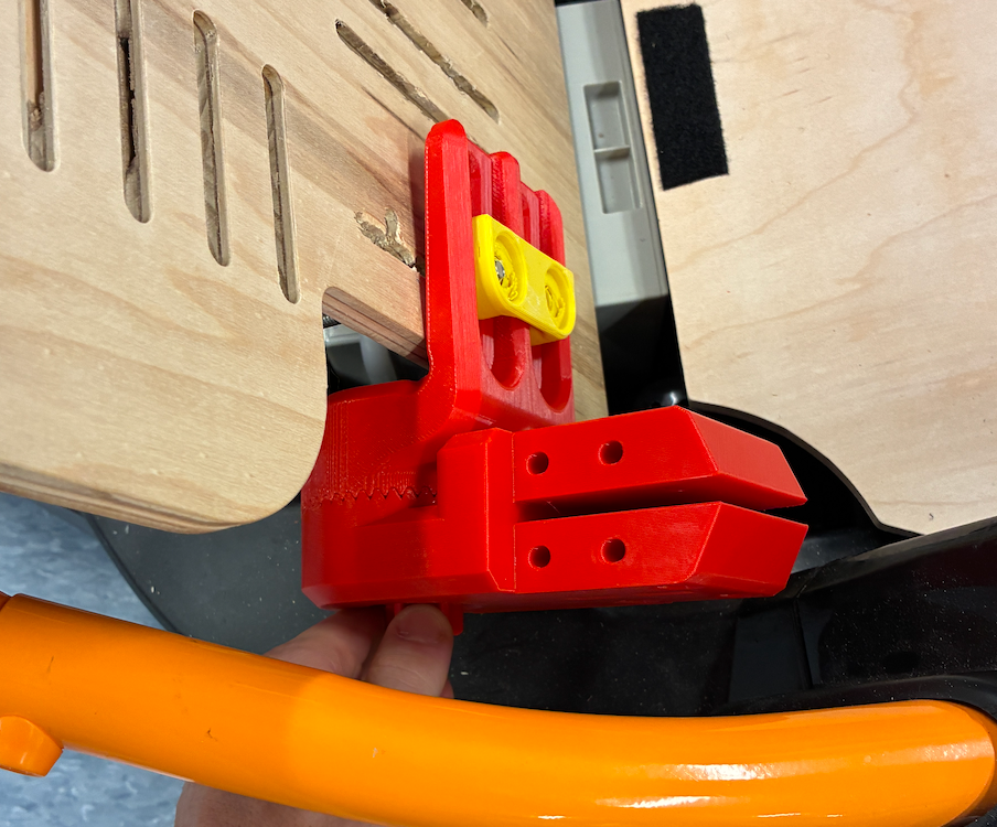
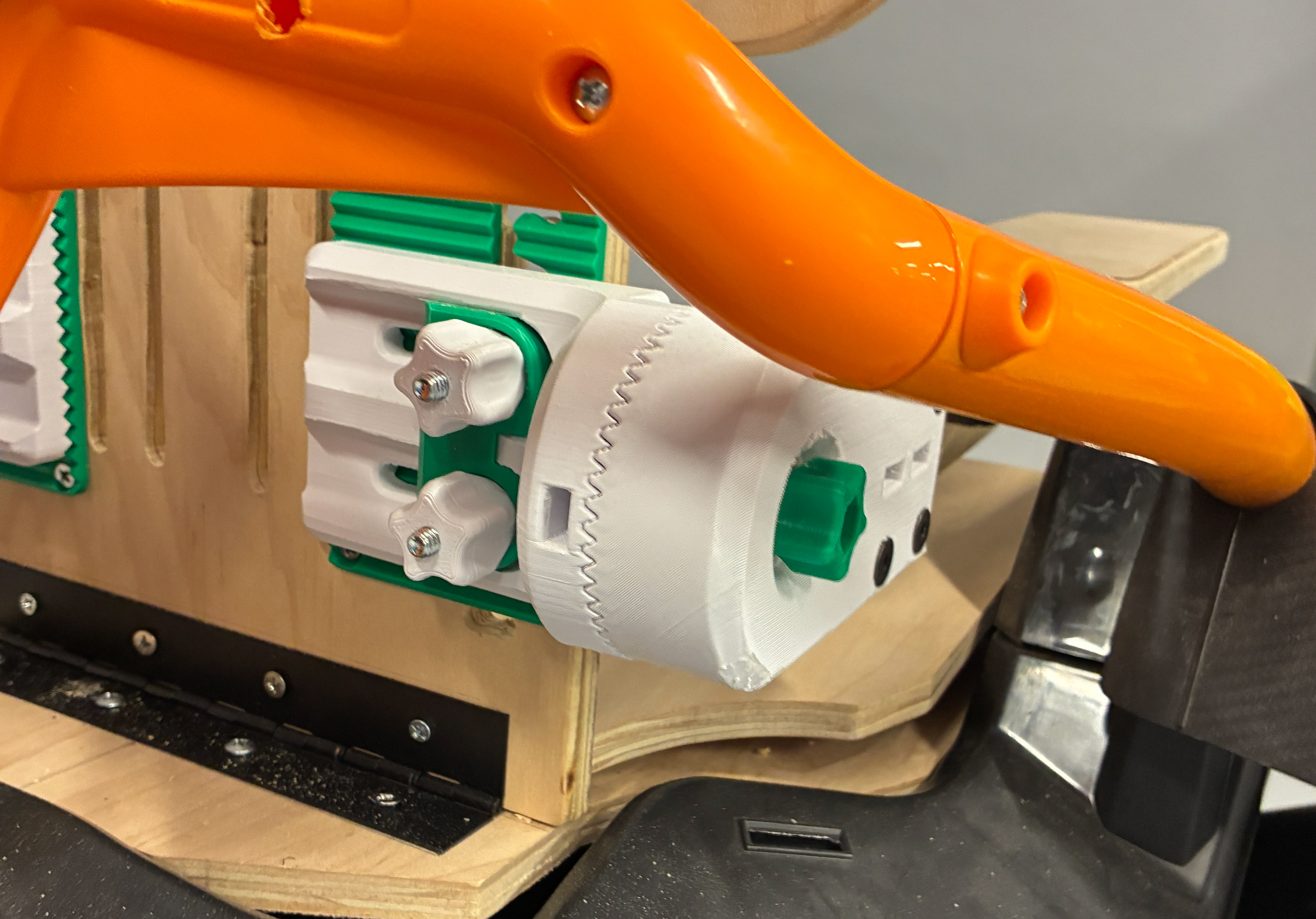
Attached Armrest Adjustment Mechanism
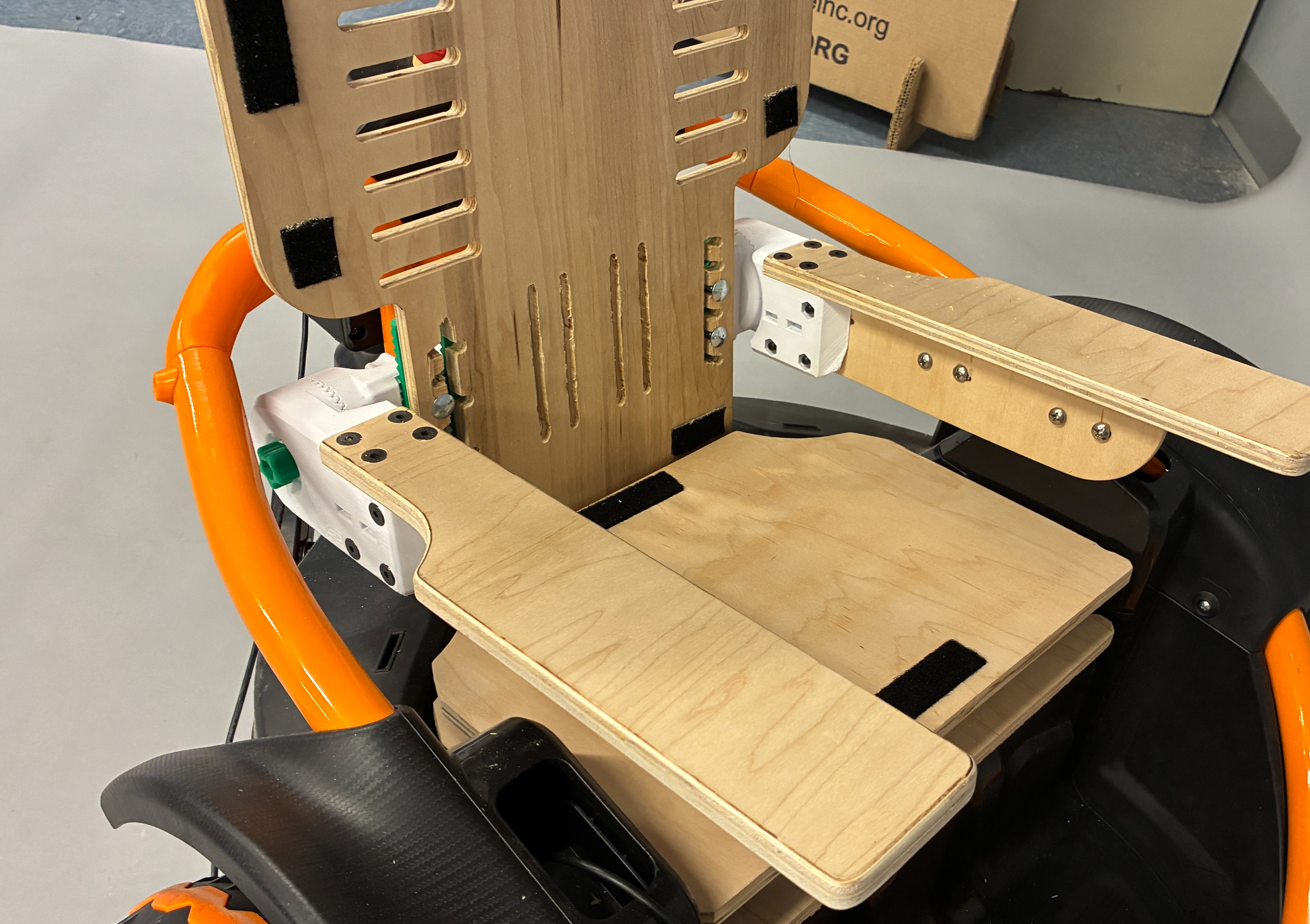
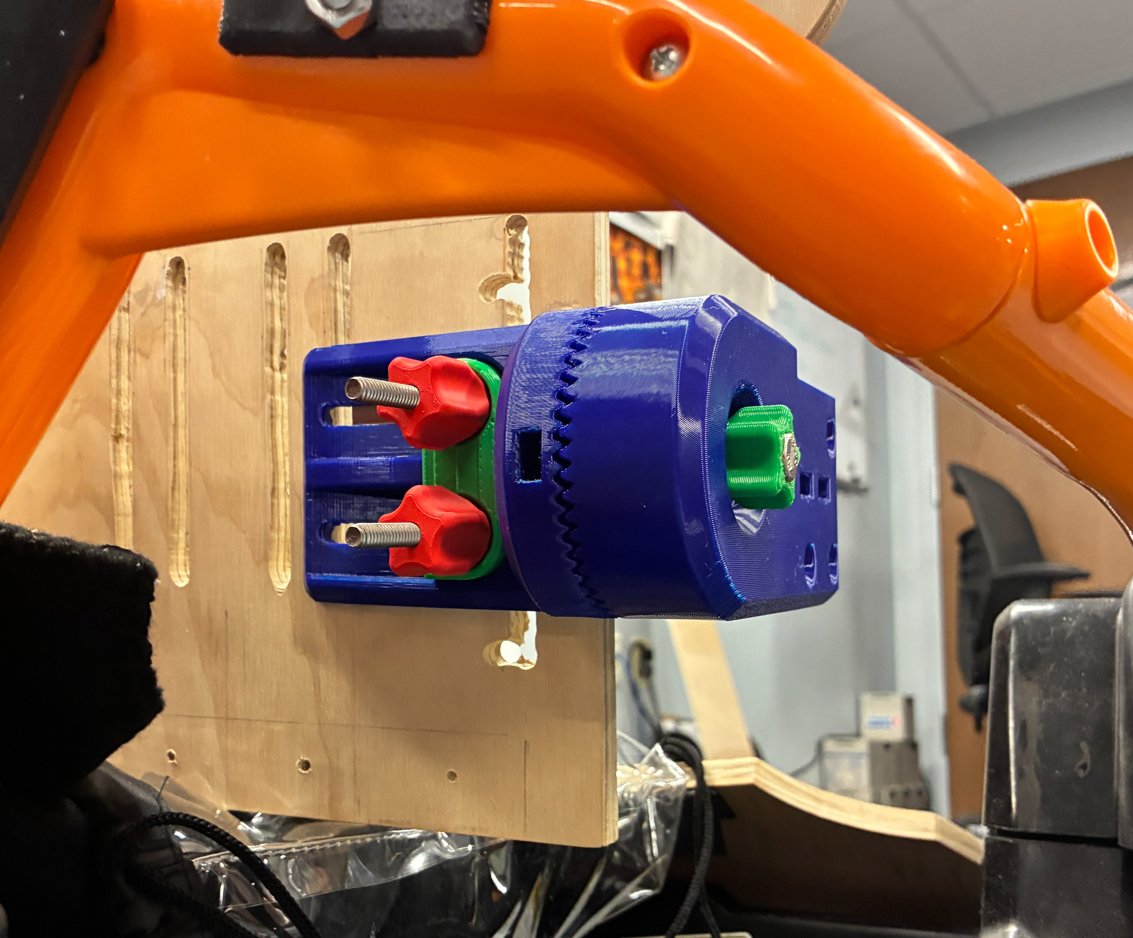
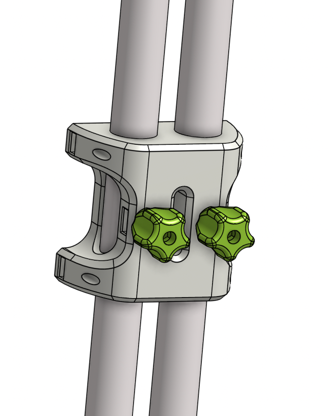
Both Arms Armrest Prototype Assembly (Seventh Prototype)
Headrest Process
The other component of the Wild Thing redesign was creating an adjustable headrest, allowing for adjustability in the headrests height and horizontal depth. To keep costs low, the idea was to use PVC and printed parts with a similar knob system.
Initial Headrest Backpack Model
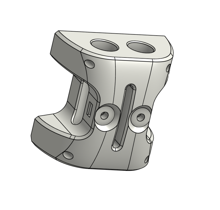
My first step was to create a piece that allows the PVC to mount to the back of the seat, this piece will also allow for the horizontal adjustment, utilizing a plunger clamping system with the knob.
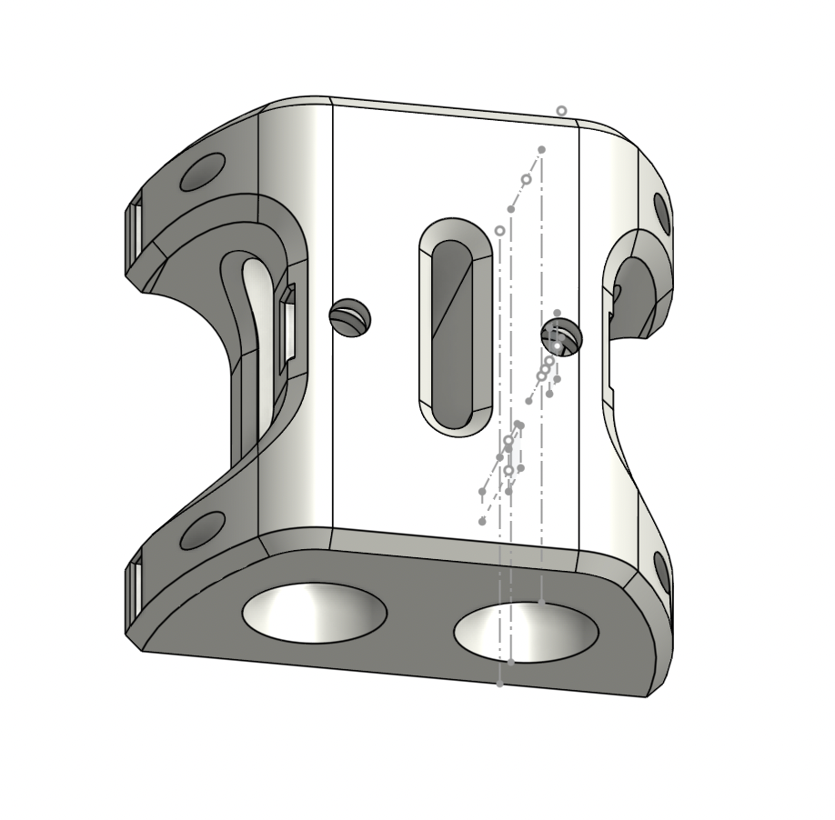
Updated Model With Flanges For Mounting
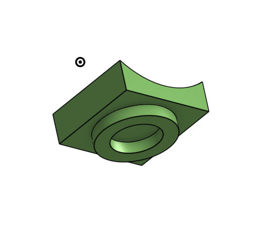
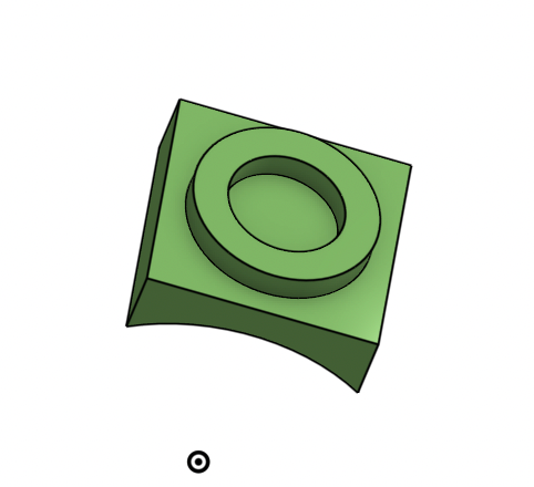
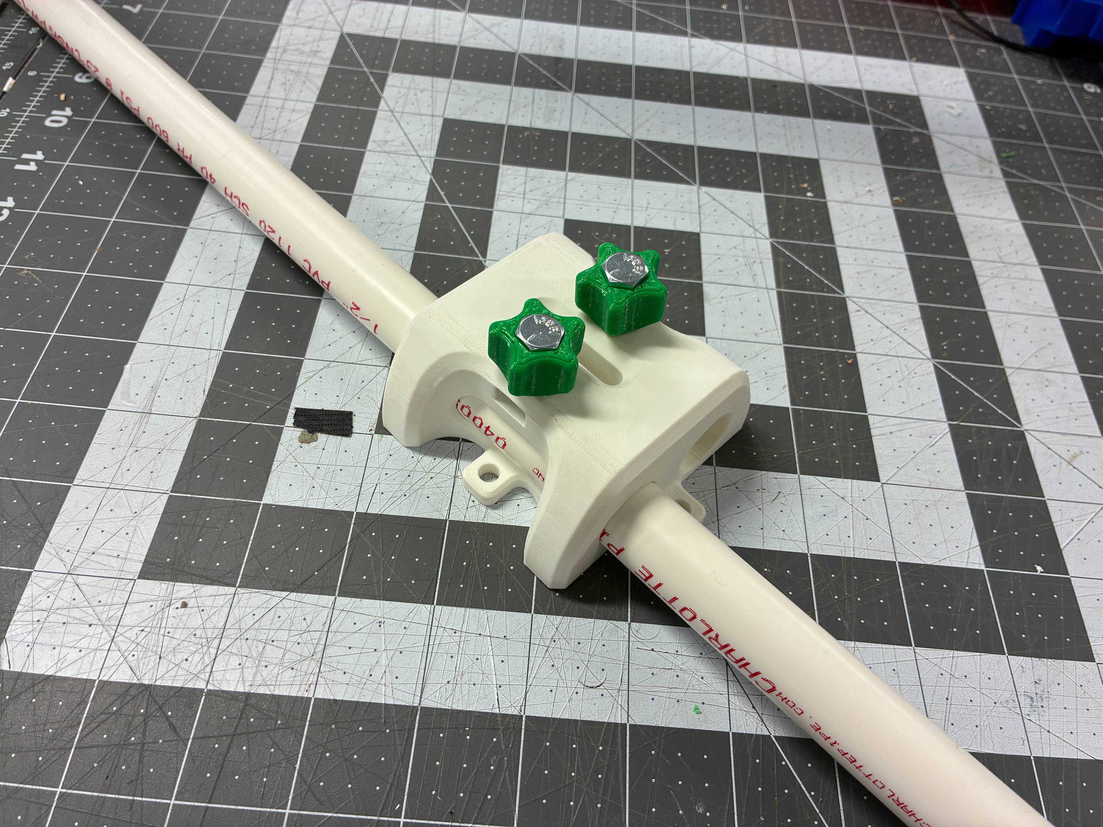
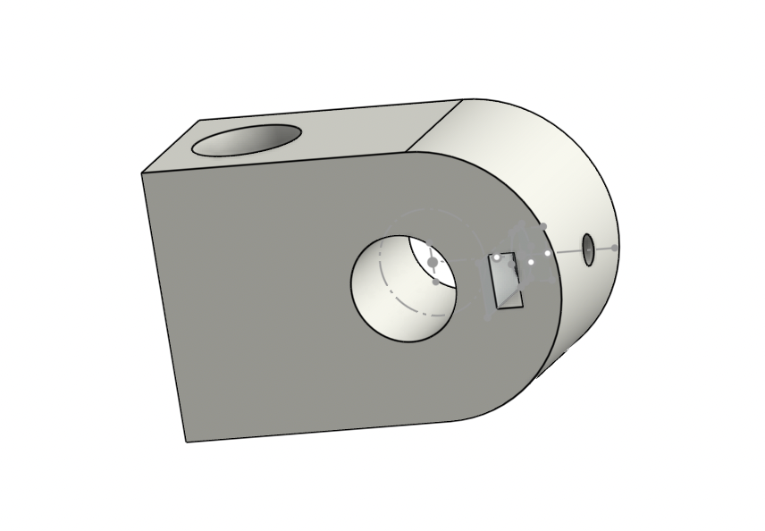
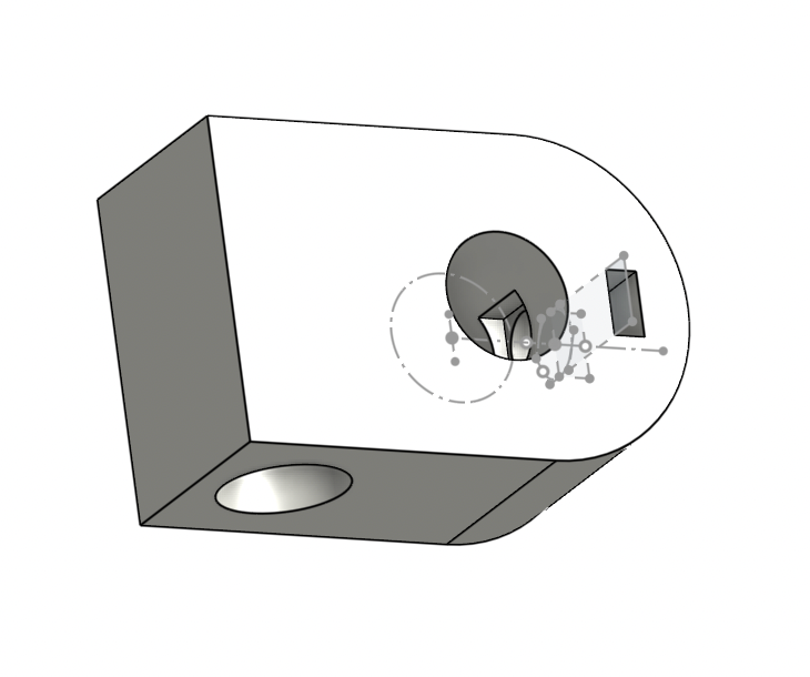
PVC Securing Push Attachment
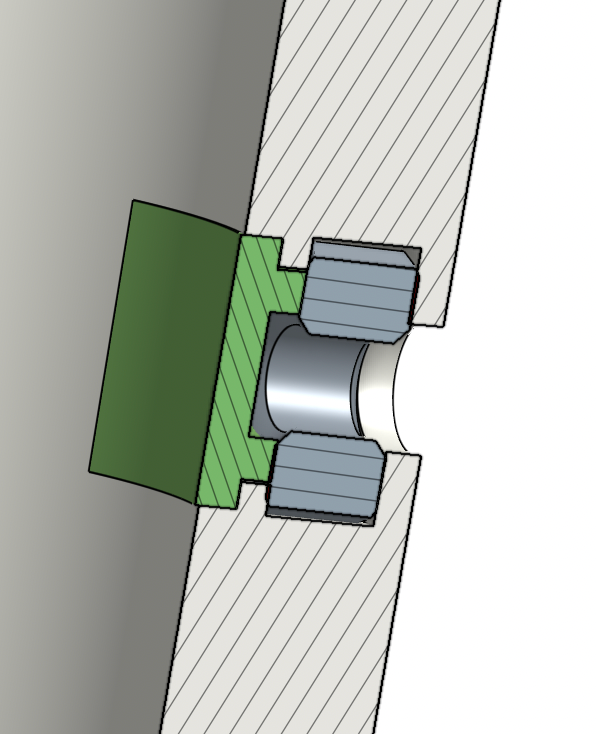
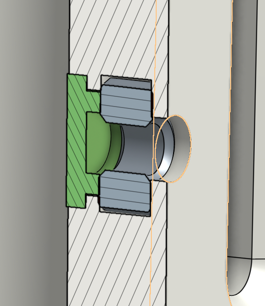
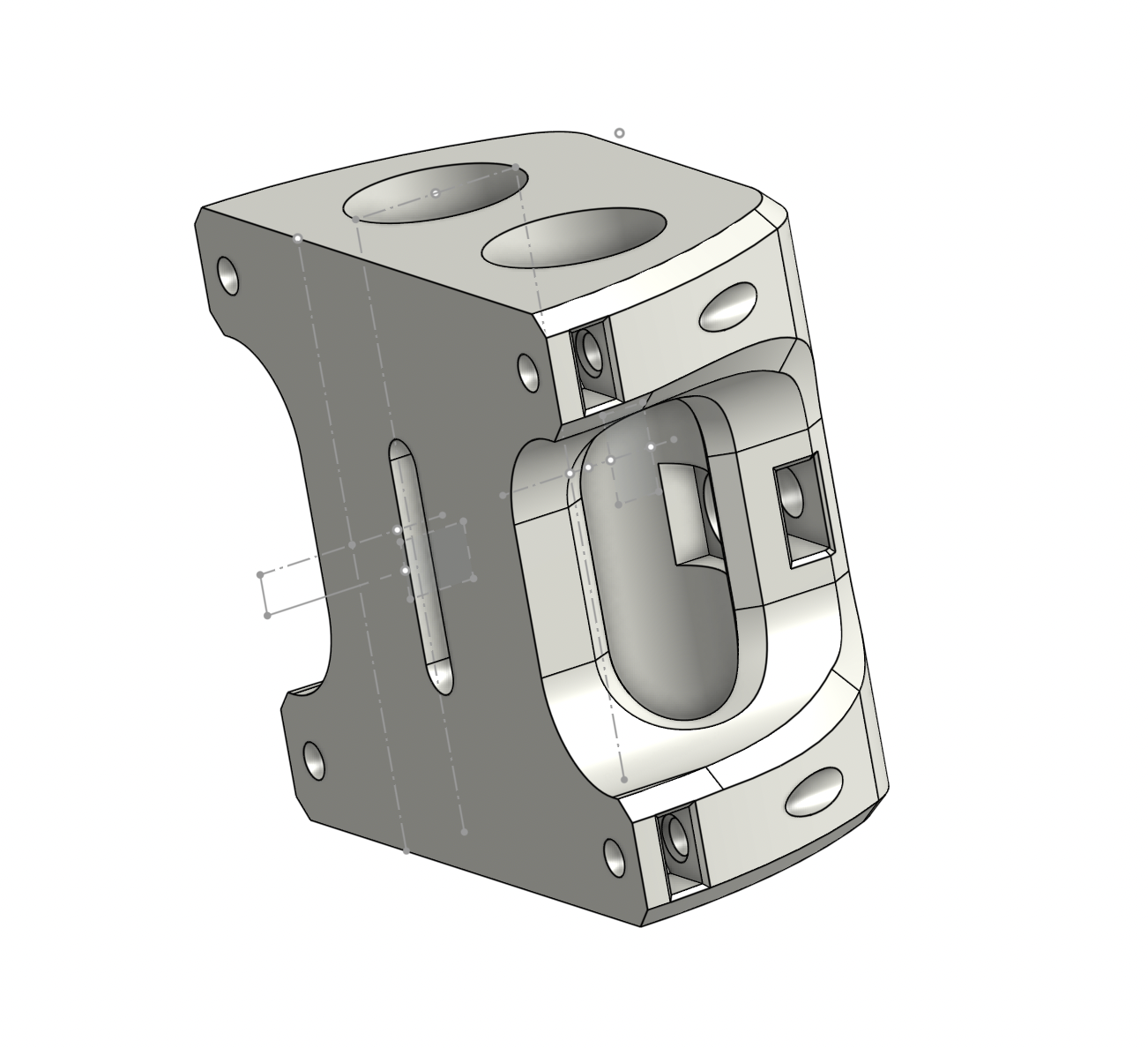
PVC Securing Mechanism Section View
The PVC plunger (green) is placed in a cutout behind a captive nut, when a bolt (attached to a knob) is screwed into the nut, the plunger is pushed tightly against the PVC, securing it in place.
First Prototype
Mechanism Example
Mechanism Example With PVC
First Prototype With PVC
It was decided after the first prototype that the flanges were not the best mounting mechanism. In order to print the part on a stronger face and improve surface area, four captive nutes were added the the piece which would attach the seat back via a counterbore and bolt on the opposite side of the seaback.
Updated Backpack With Captive Nuts
Updated Backpack Assembly With Captive Nuts, PVC, And Knobs
Second Prototype
The second prototype unveiled a problem, when the knob is tightened, the nut is pulled towards the face of the front of the print, causing splitting of the thin wall. In order to fix this issue while not making the part any bigger, stops were added to the face of where each knob rests after tightening, signaling that once the face of the knob reaches the face of the stop, it is tight enough. To further help the splitting the plungers were reprinted with TPU, allowing more tightening to be done before the nut pushes back. The piece was also printed at a diagonal angle, strengthening the thinner walls
Updated Model With Stops
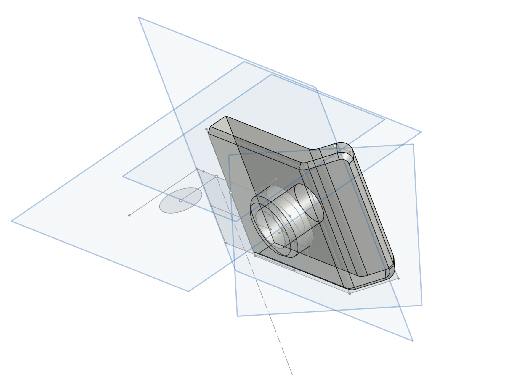
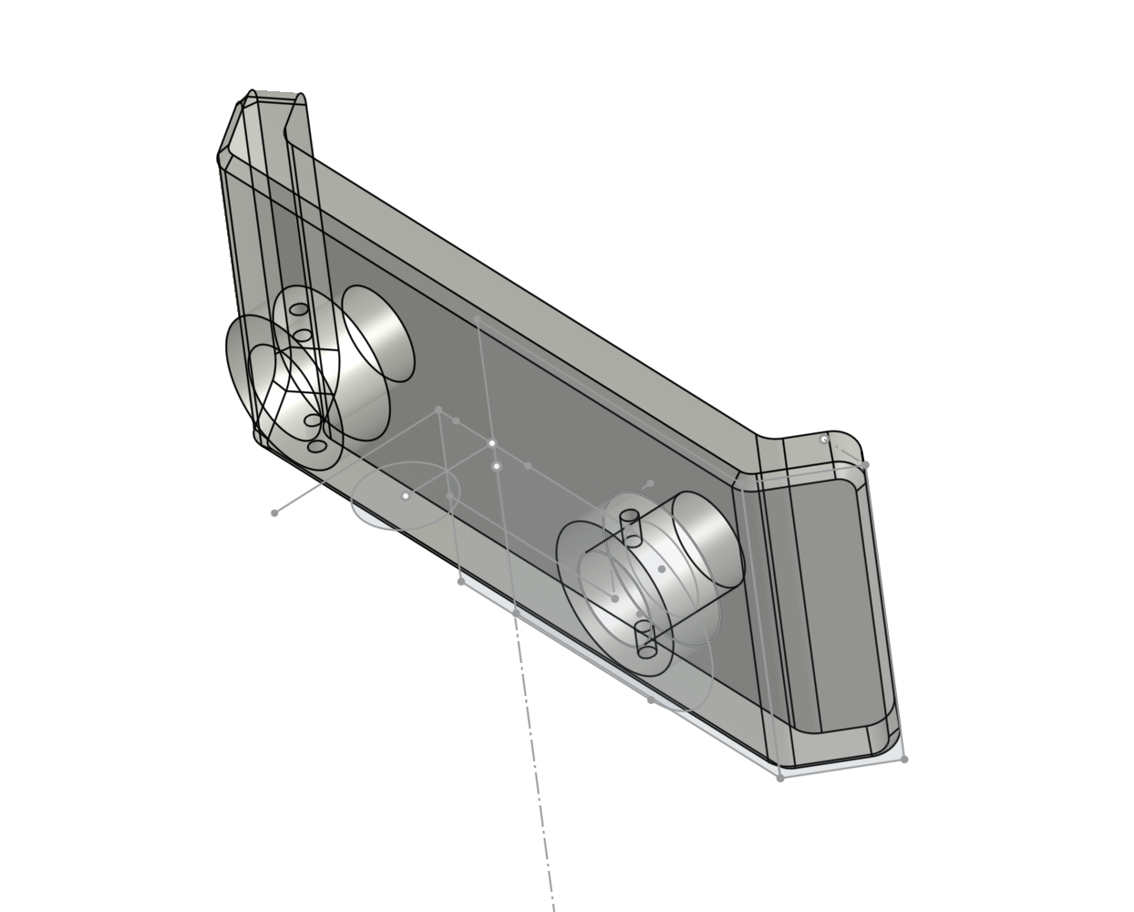
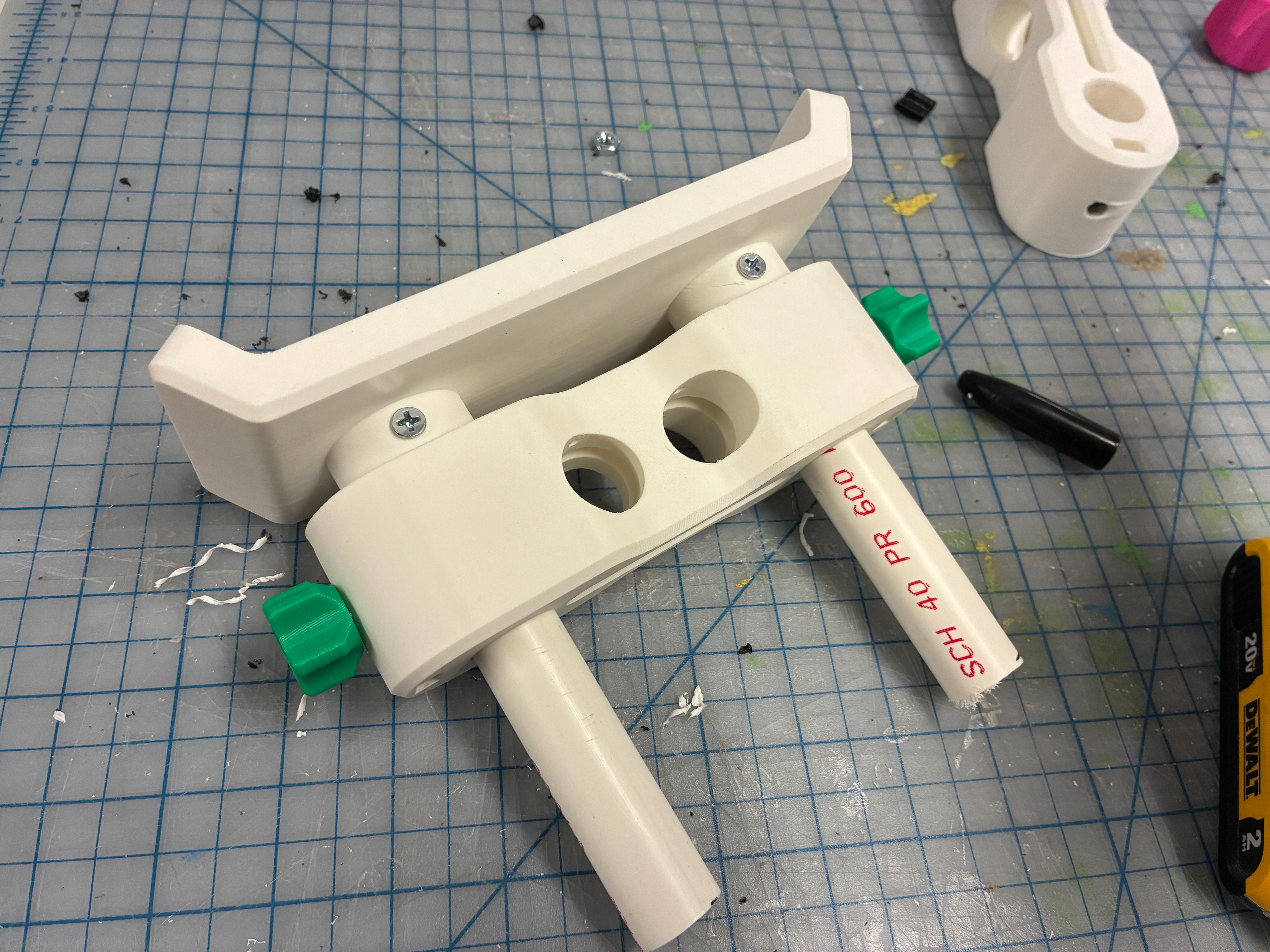
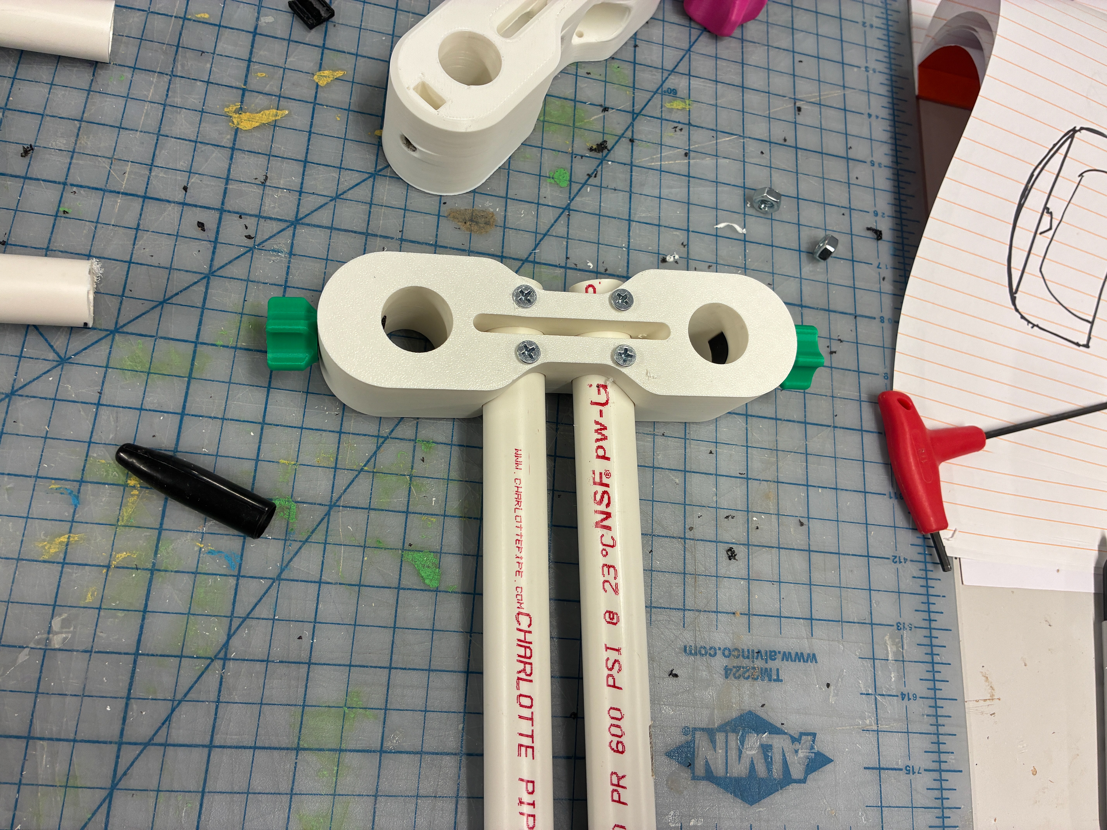
The next piece to design in this system was for the horizontal depth adjustment. This piece connects securely to the PVC rails stemming from the backpack and acts as a baseplate for the headrest and also an adjustment system for the headrest to move horizontally by supporting two horizontally stemming PVC tubes secured by the same plunger system, these PVC tubes will connect to the headrest.
Initial Horizontal Adjustment Part
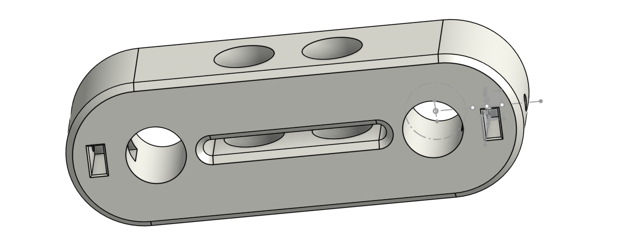
Horizontal Adjustment Part Mirrored
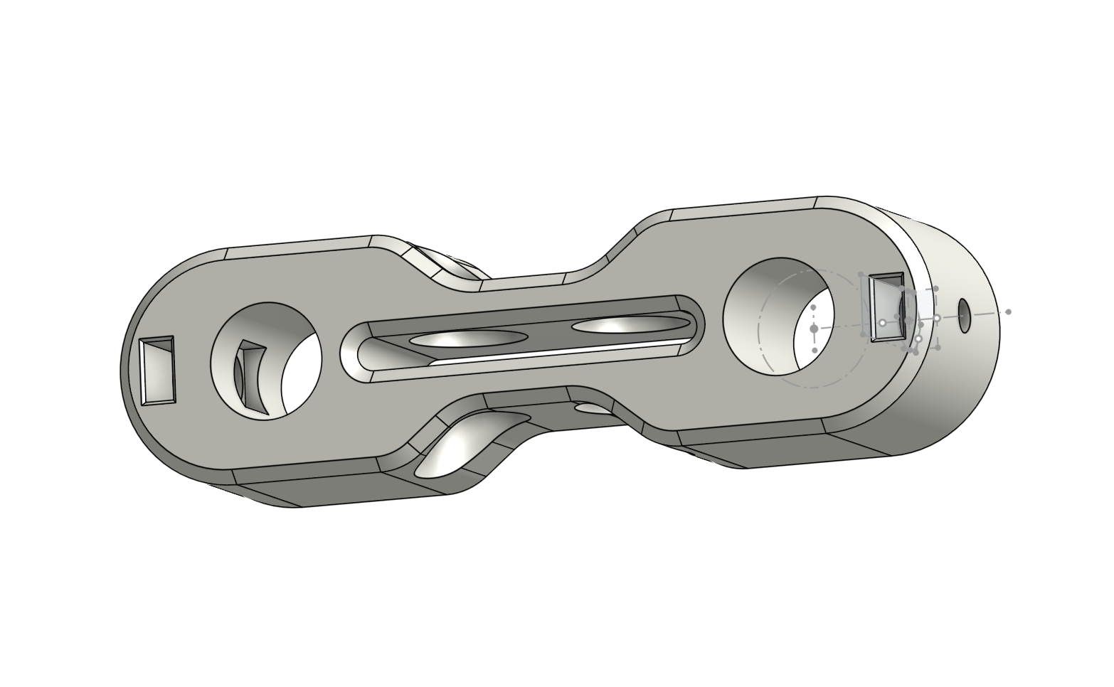
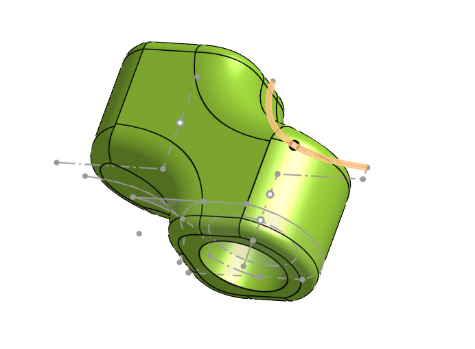
Final Horizontal Adjustment Part
Backpack and Horizontal Adjustment Assembly With Knobs And PVC
The next step was to design the headrest. The goal was to create a simple and parametric form that would be printed and cushioned by a separate printed TPU layer.
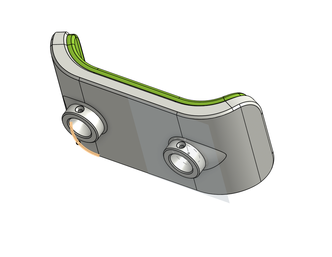
Headrest Model
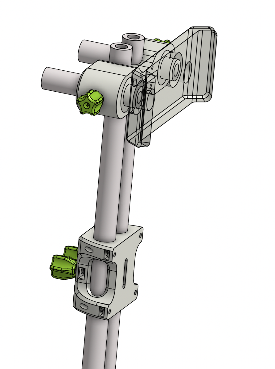
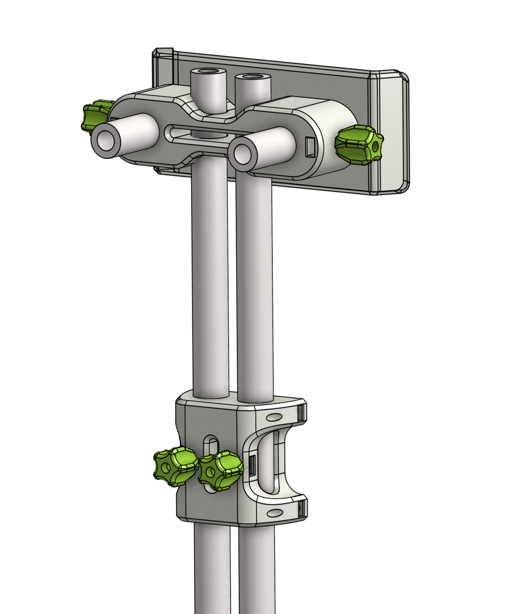
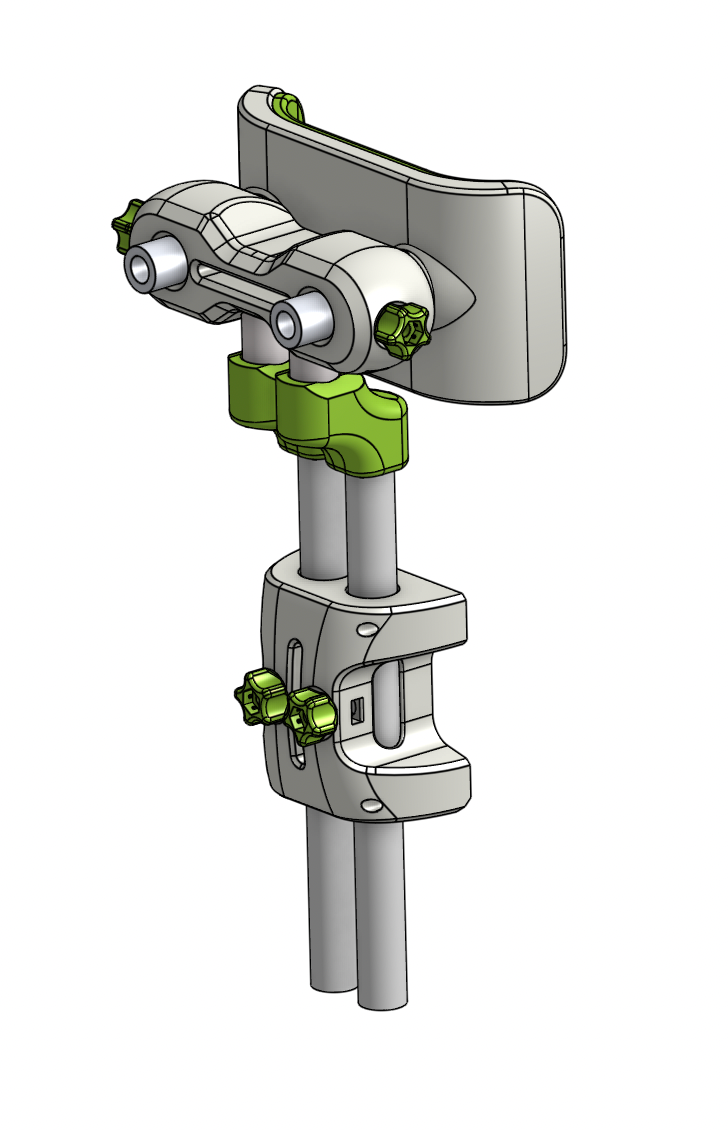
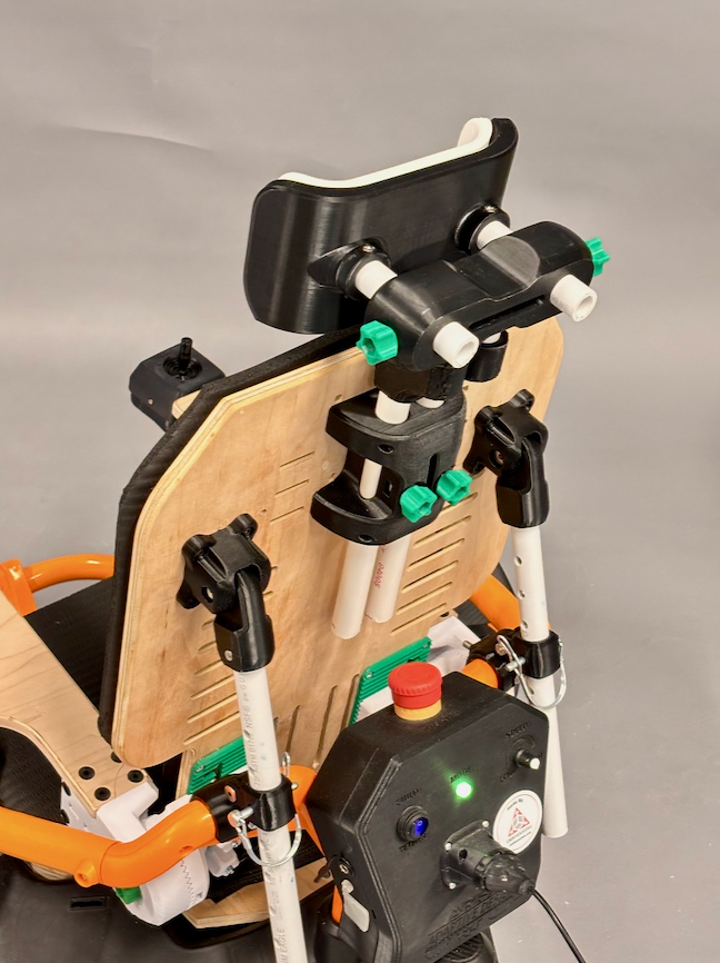
Full Headrest System Assembly
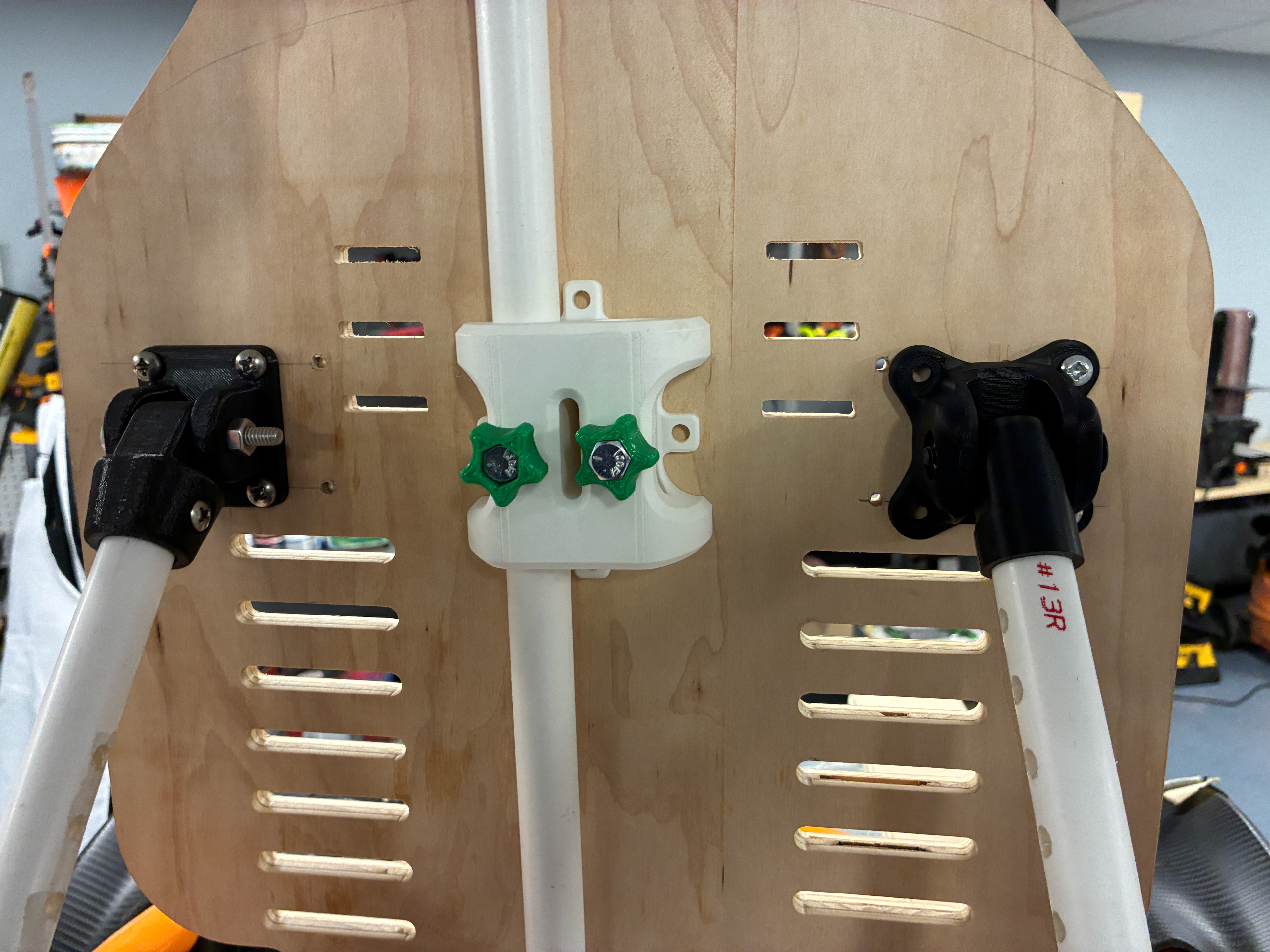
Full Assembly Being Screwed To PVC
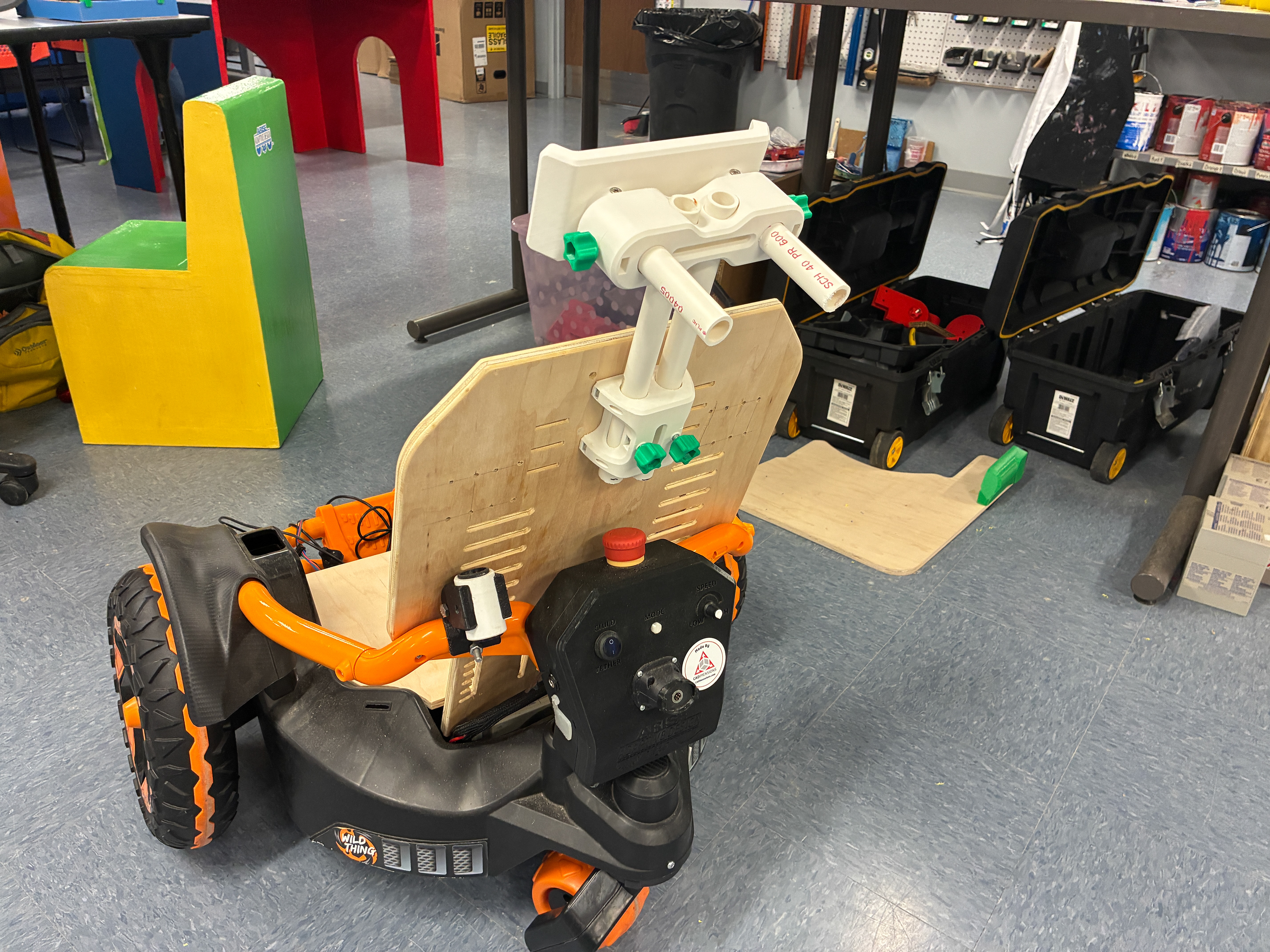
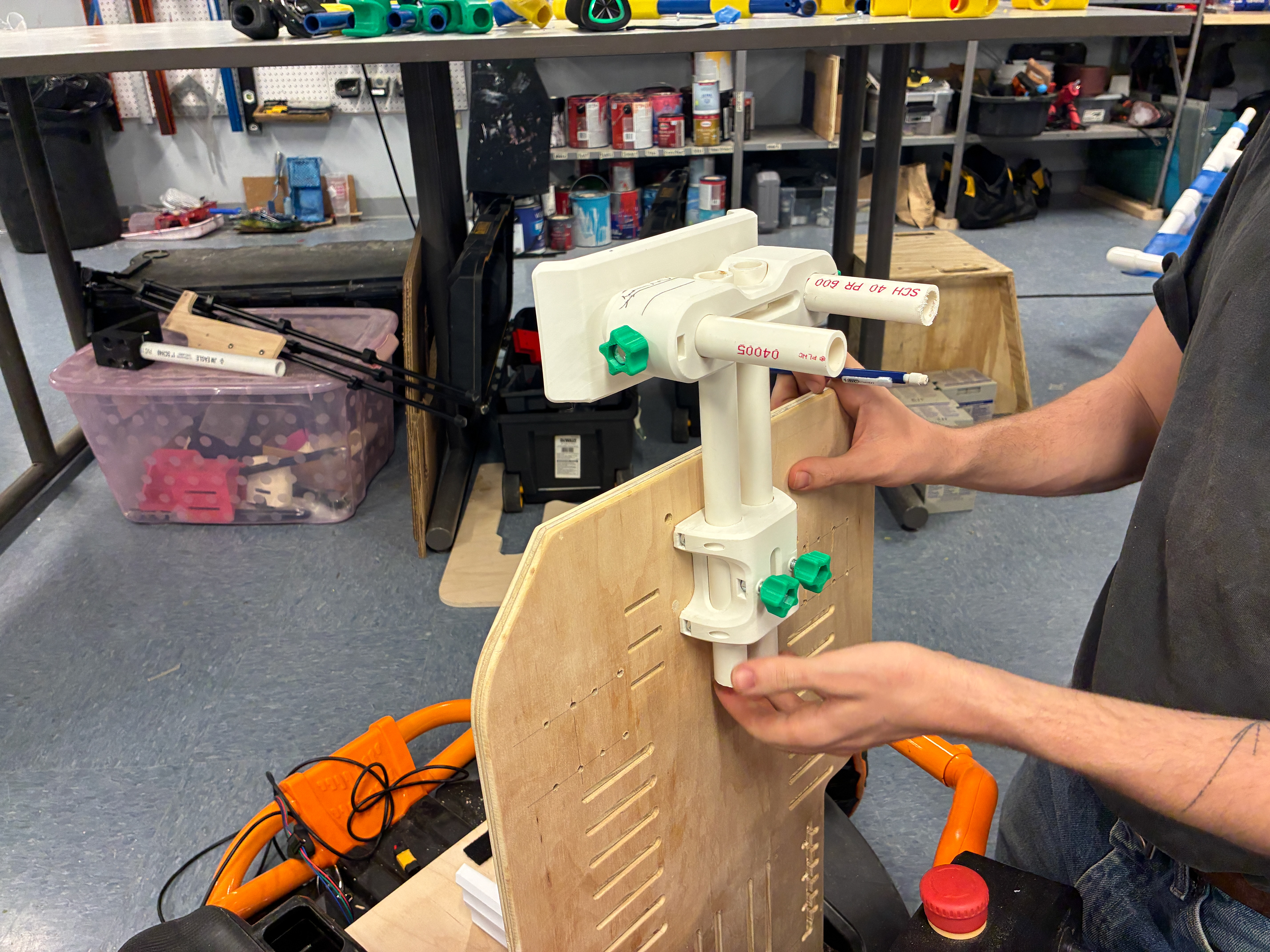
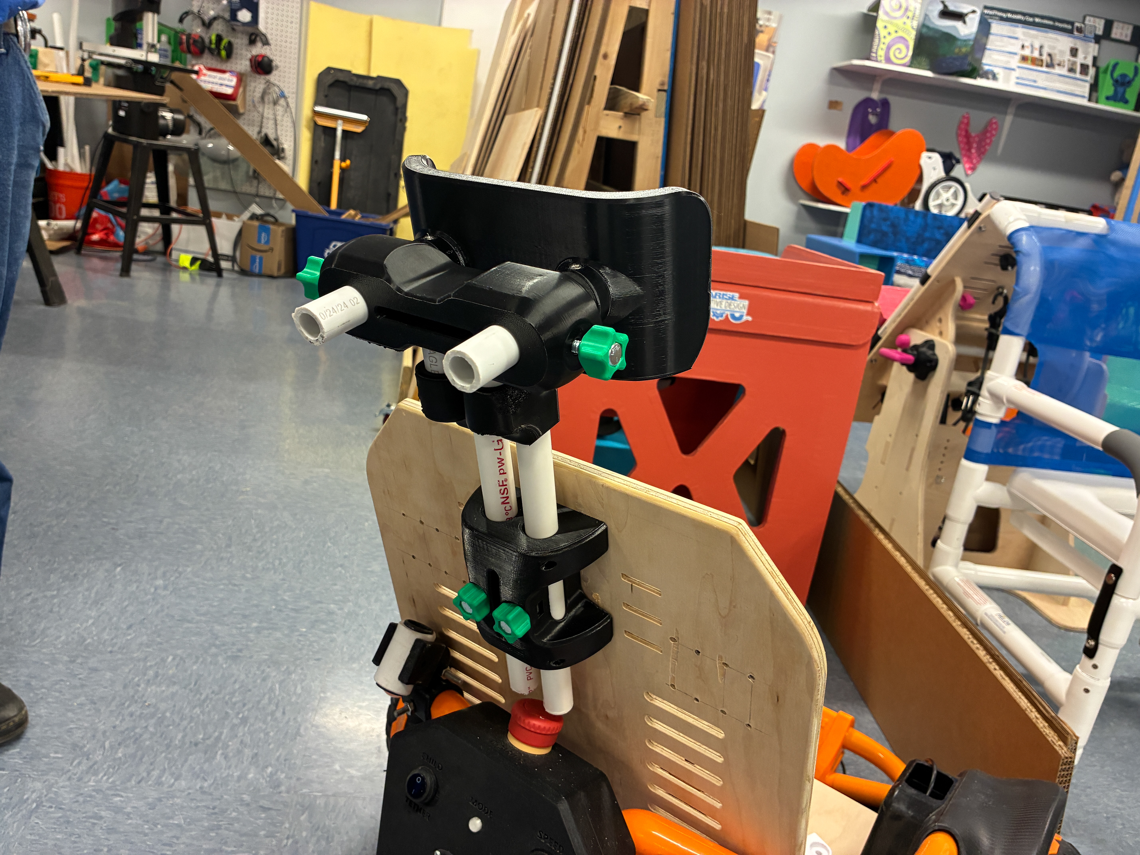
Full Assembly Mounted To Seat Back
The parts were still experiencing splitting when tightened, to further resolve, both the backpack and horizontal adjustment piece had material added to knob interface faces. The back of the horizontal adjustment piece had material removed to create an inlet for the headrest to sit flush. The main headrest piece was also updated based on real child proportion data.
From the first prototype it was realized that the headrest needs to be set back from the face of the seatplane to comfortably fit a head. Instead of adding more material to the backpack to push out the PVC, an angle offset piece was designed (below) to offset the headrest from the seat back proportionally.
Updated Backpack
Updated Horizontal Adjuster
Angle Offset
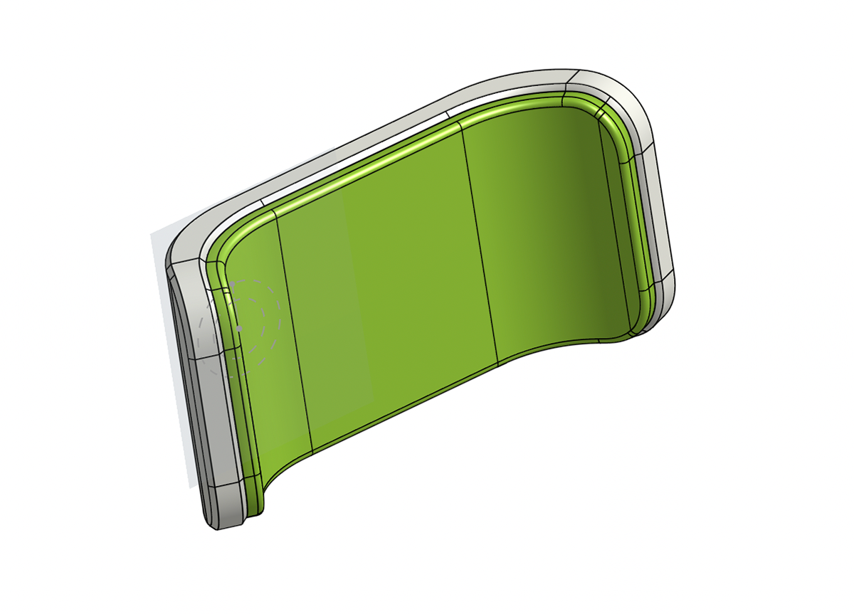
Updated Headrest With TPU Layer
Updated Assembly
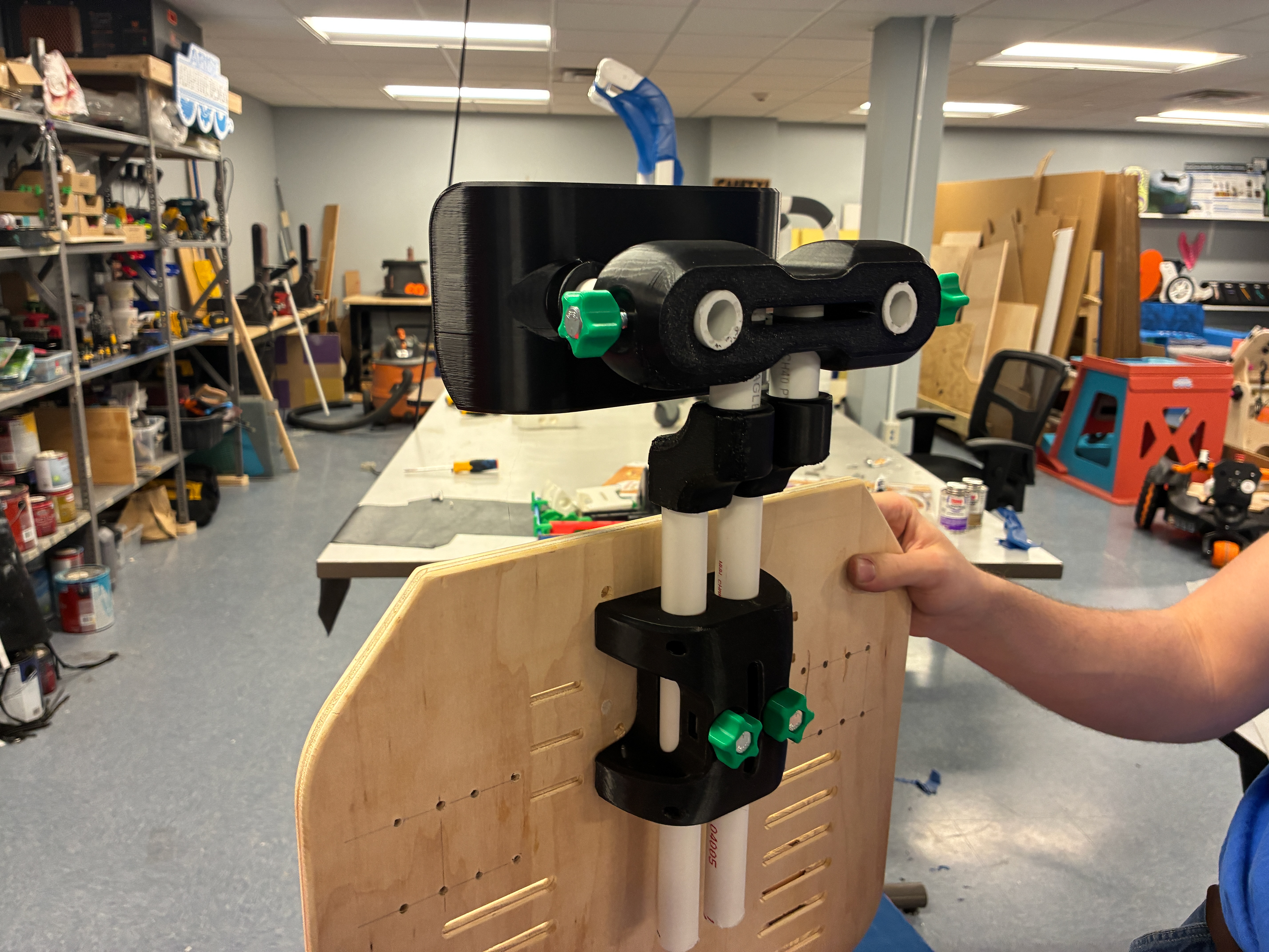
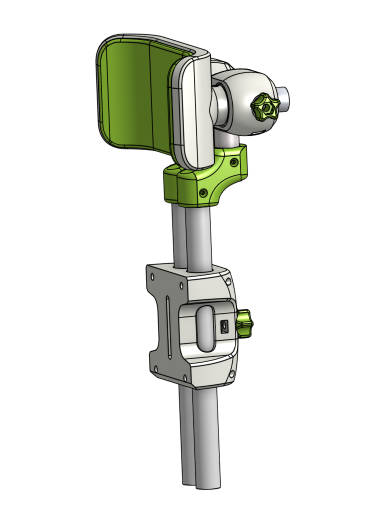
Full Updated Assembly
Backrest Height Adjustment Demonstration
Test Drive
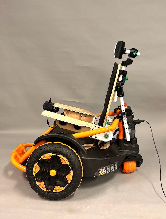
Full Assembly
Full Assembly Taking A Stroll
This project is still ongoing...
More pictures and updates will be posted accordingly.
Thanks!